
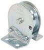
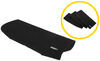
Pulley Mounting Bracket for Roadmaster InvisiBrake Flat Tow Brake System
(16 reviews)
Price: $30.68
In Stock
Pulley Mounting Bracket for Roadmaster InvisiBrake Flat Tow Brake System
Item # RM-8700-PBC
Our Price: $30.68
Will this fit?
To see if this custom-fit item will work for you please tell us what vehicle you'll use it with.
In Stock

- All Info
- Reviews (16)
- Q & A (0)
- Videos (2)
- Photos
Roadmaster Accessories and Parts - RM-8700-PBC
- Tow Bar Braking Systems
- Hardware
- Brackets
- Roadmaster
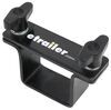
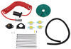
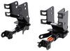
Helps you install the pulley mechanism for your Roadmaster InvisiBrake in a vehicle that doesn't have a suitable mounting location in the firewall.
Features:
- Provides a proper mounting location for the pulley of the Roadmaster Invisibrake
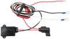
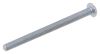
- Includes installation hardware
8700-PBC Road Master Invisabrake Pulley Installation Bracket
Installation Details


Video of Pulley Mounting Bracket for Roadmaster InvisiBrake Flat Tow Brake System


Videos are provided as a guide only. Refer to manufacturer installation instructions and specs for complete information.


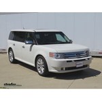
Video Transcript for Roadmaster InvisiBrake Supplemental Braking System Installation - 2010 Ford Flex
Today on our 2010 Ford Flex, well be installing the Roadmaster InvisiBrake Supplemental Braking System part number RM-8700. Were going to begin here by showing you this particular vehicle has adjustable pedals. We need to make sure that the pedals are adjusted so that they are as close to the seat as possible. Once you have this adjusted, you will not be able to use your adjustable pedals any longer once you install the InvisiBrake system. Next, were going to go ahead and choose the location where were going to mount the InvisiBrake controller box. In this case, were going to mount it underneath the driver side seat. Its best to push it forward as far as possible, that way, the passenger and the rear seat does not kick or damage the box. Before we drill any holes, we need to make sure when choosing a location that theres nothing around it that could be damaged when we mount it or route our wires to or from the box. When we have our location of our box chosen, next well go up here underneath the dash.
We need to trim some of the plastic away as well as some of the insulation so we can gain access to the firewall itself. Well be needing to drill a hole through the firewall to route some wires and tubing through as well as to mount our bracket that will hold the cable that will run from the controller box up to the brake pedal. Now, were going to go ahead and take a small pilot hole bit and drill a hole through the firewall. Next, were going underneath the vehicle. We can show you where the pilot hole has come through the firewall. Then, were going to need to take our larger bit to drill a larger hole that we can put a plastic grommet through the firewall.
Were going to install a Snap bushing grommet which is part number SWC8057.z Next, were going to go ahead here in the driver side door area. We need to remove the threshold as well as the kick panel. Well need to remove these to run our wires from the controller box out the hole that we just drilled in the firewall. Now that weve got our wires as well as our quarter-inch tubing pulled up here underneath where the pedals are, were going to go ahead and feed them through the grommet that we put in the firewall earlier. Now, you will need to push the breakaway switch which has the black and white wire through the opening first because this has the largest connector. Next, well route the rest of our wires through the grommet, the four pole wire, the red and the black wires and the quarter-inch airline tubing.
Well zip tie these wires together to keep them in a nice neat bundle. Now, were going to actually need to push one of these small wires right here back from the engine side back into the drivers compartment. This is the wire well be tying in with the cold side of the brake switch. This will send the signal up to the tow vehicle telling you when your brakes have been applied or if theres a problem and your brakes had become stuck on. Now, to actually route the wires from the controller box up to the area where we need it, were going to use a section of old airline tubing to help pull our wires through the threshold area as well as up underneath the carpet. With the airline tubing, its a good idea to put some electrical tape on both ends to keep it off any dirt or debris while youre routing this line. The final wire that well need to run is the wire thats connected to the air cylinder. Well route this cable up in the same manner that we routed the other wires as well as the quarter-inch air tubing that eventually came out through the hole and the firewall.
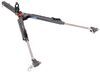
Now, we chose to mount the air cylinder underneath the carpet here in between the front and the rear door but to gain access to this, well need to remove a couple more interior panels. This will allow us to pull the carpet back and off and put our air cylinder into place. Well secure the air cylinder with the clamp that is supplied with the kit as well as the self-tapping screw. Now, youll notice that theres a little push fitting on the side of the air cylinder. This is where the 8-inch diameter air tubing will tie in that well ultimately tie in with the back of the controller box so you want to make sure that you put the 8-inch air tubing in the air cylinder before putting the carpet and interior panels back into place. Simply push it into the fitting so that it locks in firmly. Once thats done, we can go ahead put the carpet back in place as well as any interior panels that we may have removed to gain access. Now, were ready to go ahead and make some connections to the back of the InvisiBrake controller box. Well need to install a quarter-inch vacuum hose section onto the fitting first then well need to plug in the two other electrical connections into their appropriate location. Making sure that they fully lock into place and that the locking tab secures them. Make sure that the 8-inch tubing has an even cut on the end. The little tubing, well simply push into the fitting at the back of the box. If you put in the electrical tape on any of the airline tubings, remove that before you put it into the quarter-inch vacuum hose here that connects into the back of the controller box. Now, well go ahead and just get our wires up making sure nothing becomes bent or kinked along the way and were going to go ahead and mount our controller box to the floor of the vehicle. Were going to use a self-tapping screw on one side. Well use a bolt and a locking nut on the other side. Now on the side that actually comes through the floor board, we actually went ahead and used a little bit of silicone sealing to seal off the connection part number LT37467. Weve gone ahead and route all the cable thats connected to the air cylinder along the threshold and up here up underneath the dash. Well put the cable through the pulley by simply pulling out the clip on each of the two pins unraveling the cable through the pulley. Well then put the pins back in as well as the clips to hold the pins in place. Now with this done, our cable is routed through the pulley and well need to mount our pulley to our optional bracket to get our pulley over close enough to be behind the brake pedal. Now well go ahead and attach our bracket here to the pedal. Well do this by using the two bolts as well as the lock nuts that come with the kit. This will go around the pedal. You want to make sure that where you choose the mount the bracket on the brake pedal that it will not impede the use of the brake pedal itself. Now because of how the firewall is shaped, were going to need to use the Roadmaster Optional Pulley Mounting Bracket for the Roadmaster 8700 InvisiBrake part number RM-8700-PBC. The pulley itself will attach to the bracket using screws and lock nuts. Now you notice here that theres a ground stud thats part of the firewall. Were going to actually use this as one of our mounting locations for our optional pulley bracket as well as some self-tapping screws that will be screwed through the firewall to help hold the bracket in place. Now well need to go ahead and connect the end of the cable to the bracket thats on the brake pedal. We want to make sure that we have about a quarter-inch of free play on the cable once the cable has been adjusted. Now once you have the pulley bracket as well as the pulley mount location figured out, youll need to take the bracket that holds the end of the cable and youll attach it to the firewall using two self-tapping screws. Well go ahead and use zip ties to help secure up the wires. Youll also notice that once we go and fold the carpet back that were going to need to trim out a small section of this. That way, it clears the pulley and the cable. Now for that little wire that we ran from inside the engine compartment back into passenger compartment, this is the wire that were going to tie in with the cold side of the brake wire switch so well use our test light and then probe the back of the wires off of the brake light switch. Now in our case, were looking for the purple and white wire. Well simply use a quick splice connector tying the black wire to the purple and the white wire and then we can put our interior trim panel pieces back into place. Now were done inside the vehicle so now were going to go ahead and move up here underneath the vehicle where all of our wires have been pulled through the firewall. Well go ahead and use a few zip ties to keep the wires into a nice clean bundle. Well then need to go ahead and route them to the appropriate locations. Once we have all of our wires bundled up, were going to again use an old section of airline tubing to help hold the wires up into their proper location. As you can see here, we also used some half-inch diameter wire loom which is part number 459075-1 to protect the wires as they come out of the firewall up into the engine compartment area. Well go ahead and use a little bit of electrical tape and a few zip ties to help secure this to the wiring bundle. Next, we need to remove the front fascia. To do this, well need to remove two 10-mm bolts as well as four push pin fasteners. Next well going to the wheel wells where there will be three 5 -mm screws that need to be removed. Underneath the vehicle, well be removing seven 5 -mm bolts. Then there are two push pins under the fascia just below the license plate. With the hardware taken out, it would be a good idea to get an extra set of hands to help lift the fascia off and away from the vehicle. Now this vehicle does have lower fog lights which need to be removed. Be careful not to break the tabs when removing them. Now that weve got the front fascia removed from the vehicle, well leave the four pole wires in the engine compartment to be connected later. Well go ahead and use an airline tubing to help place the wires to their proper locations. Now well route the remaining black and white wires from the breakaway switch and the black wire, well just connect to the brakes themselves. Well route these in the same manner we routed the wiring harness previously installed on this vehicle. Now that weve got our wires pulled out here to the front of the vehicle, well go ahead and mount or breakaway switch to the bracket that was installed earlier when we installed the base plate kit. Well go ahead and attach our breakaway switch to this bracket using a nut and bolt. Once our breakaway switch has been attached to the bracket, well go ahead and put our connection point together here by simply pressing the two ends together. Once we have our connection point made, were going to go ahead and use a little electrical tape to make sure that the connection stays nice and tight. Were going to then go ahead and take another self-tapping screw and one of the brackets that came with our base plate kit. Well attach it to one of the two prongs that are mounted to the cross member of the base plate. Now were going to go ahead and take some electrical tape and tape up the four-flat end connector with the black wire that will go up to our signal on the dash of our tow vehicle telling us when our brakes had been applied on our towed vehicle. Well again go ahead and use a section of half-inch wire loom to protect the wires as they come out of the front of the vehicle. Well go ahead and bundle up any excess wiring and well go ahead and use a few zip ties to attach it here to the cross member of the base plate. Well then snip off any excess zip ties to give it a nice clean look. Now that weve got all these connections made, were going to need to trim out a small area on the grill on the front fascia to allow for our breakaway switch to fit through the grill. To do this, well simply use a rotary tool with a cutoff wheel bit. Once you have the grill trimmed, its a good idea to get an extra set of hands to put the front fascia back in place. Next were going to need to tie in the four-flat wiring that came from the InvisiBrake controller box to the four-flat wiring thats up here underneath the hood. Now well go ahead and pull up the excess slack that we left from the earlier installation. Well go ahead and snip this four-flat in half because well be tying in our new four-flat wiring with the original four-flat wiring using butt connectors. Well be connecting it with color to color. Now that weve tied the new four-flat wiring in with the existing four-flat wiring using the butt connectors, well go ahead and use some electrical tape to help secure everything. Next well need to install our inline fuse that goes to the bundle of wires that have the red and the black wire in it. Well go ahead and connect our inline fuse to the red wire side. Once we have our inline fuse connected to the red wire, well need to put a ring terminal on the end of the black wire. Next well install our fuse in the fuse holder and make our connections to the battery. The red wire will go to the positive side of the battery and the black wire will go to the negative side. The final connection that well need to make up here underneath the hood is putting in the check valve as well as the T-fitting in the vacuum line coming off the brake booster. The kit does come with two different sizes. You will need to make sure that youre using the proper size to tie in with the vacuum line. Now once youre sure that you have the correct size T-fitting and check valve, well need to go ahead and cut the vacuum line here. Well actually cut the vacuum line in two different sections. Well then put on the T-valve then a piece of rubber hose then the check valve. In this case, you want to make sure that the red side of the check valve goes towards the engine in order for the check valve to work properly. Now that we have our T-fitting in place, well go ahead and take a small section of rubber hose and slide it over the T-fitting and then put our quarter-inch nylon tubing into that. Now that weve got the quarter-inch airline tubing tied in with the vacuum line, well go ahead and use a few zip ties to help secure everything here underneath the hood. Now well move out to our RV and route our monitoring system wire. On this particular RV, well be using the storage areas to run our black wire from the rear of the RV. Well use the old section of red airline tubing to help us with the routing. Well run it to the seventh pole at the rear and zip tie it in place. Well again use some wire loom to protect the wire in areas that may have some sharp edges. Now well continue to run our wire up to the front of the vehicle hiding our wire in the storage compartments along the way. Now because of the length of our motorhome, we had to add a little extra wire to the wire that runs from the rear of the motorhome up into the drivers compartment. Well do this by simply using a butt connector and some electrical tape to secure the connection. Next well again use a section of our red airline tubing to get our wire from the engine compartment to underneath the dash in the cab of the RV. Once that is done, well zip tie our wires down outside. Now we need to choose a location that well be mounting the LED light as well as mounting the audible alarm circuit board. Now you can see that theres some switch panels right here on the dash that are blank. Were going to go ahead and pop one of these out and drill a hole in it the size of our LED light. Then well install the LED light from behind. Next were going to need to connect the wires from the LED light as well as the audible circuit board. The two red wires will be connecting in with the black wire that we ran from the rear of the motorhome. Well do this using a butt connector. Now for our ground wire, well be connecting the white and the black wire together using a butt connector and then were going to go ahead and add another short section of wire just to give our self a little bit more movement where we can connect our ground wire. Now that weve got our electrical connections made, well go ahead and feed our wires back through the dash here and put the switch panel back into place in the dash. Now we can make our connections under the dash. Well connect our red and black wire to the black wire we ran from the rear of the RV. Well then go ahead and use a few zip ties to secure the audible alarm up underneath the dash as well as any excess wiring. Once thats done, well go ahead and take our ground wire with the ring terminal on the end of it and attach it to a metal portion of the dash using a self-tapping screw. Now lets go out and show you how the wires will connect from the towed vehicle to the tow vehicle. Youll see here that well be connecting our four-flat wiring from the front of our towed vehicle to the back side of the RV. Well then connect the jumper wire which is a small black wire with a male end on both ends to the small black wire that ran from the brake light switch on the towed vehicle to the black wire that we just ran up underneath the dash of our towed vehicle. The only connection left is the connection between the breakaway switch and the secure mounting location on the tow vehicle. Now lets go ahead and run through and make sure that our lights are working properly as well as the InvisiBrake itself. There you have it for part number RM-8700 on our 2010 Ford Flex. .
Customer Satisfaction Score:
92% were satisfied with this product
8% of customers were not satisfied
- Wrong item was ordered
- Product did not meet expectations
Customer Reviews
Pulley Mounting Bracket for Roadmaster InvisiBrake Flat Tow Brake System - RM-8700-PBC
Average Customer Rating: 4.7 out of 5 stars (16 Customer Reviews)
Helps you install the pulley mechanism for your Roadmaster InvisiBrake in a vehicle that doesn't have a suitable mounting location in the firewall.by: Tracy06/29/2023
The product was fine and as described but the delivery on this one was very poor it should have come in an envelope instead of a over sized box. Then it shipped right away but took over a week to get here and because it was in a box the post office had to wait until we opened again to actually deliver it.
by: Michael 01/13/2022
Made installing of the cable pulley that much easier. Highly recommend.
by: Wim07/12/2020
Seems to do the job. However, the product does not come with a protective cover, creating a danger of Future shorts if not careful with Tools around it.
by: Peter B.04/15/2019
Highly recommended for uneven floor board. Excellent product!
by: Bob 05/03/2020
Product worked as advertised.
by: Tracy 10/11/2023
by: Looks good 09/27/2017
Solid and ready to install
by: Terry 09/13/2022
by: Nathan 09/06/2022
by: Randal 08/19/2023
by: Ray07/03/2021
by: Dennis06/26/2019
Great job getting product sent to me
by: C. H.07/15/2021
by: Dennis 05/12/2021
by: Dennis06/26/2019
Just what I needed
by: John 08/11/2022
16
16
See what our Experts say about this Roadmaster Accessories and Parts
Info for this part was:

Video Edited:
Zack K

Installed by:
Steven C

Updated by:
Wilson B

Updated by:
Amanda K
At etrailer.com we provide the best information available about the products we sell. We take the quality of our information seriously so that you can get the right part the first time. Let us know if anything is missing or if you have any questions.
Product Experts Available Now!
Call 1-800-940-8924
Thank you! Your comment has been submitted successfully. You should be able to view your question/comment here within a few days.
Error submitting comment. Please try again momentarily.