
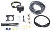
ModuLite Ultra Protector Wiring Harness w/ Integrated Circuit and Overload Protection
(8 reviews)
Price: $97.36
ModuLite Ultra Protector Wiring Harness w/ Integrated Circuit and Overload Protection
Retail:$130.38
Our Price: $97.36
You Save: 25%
Will this fit?
To see if this custom-fit item will work for you please tell us what vehicle you'll use it with.
Thank you! Your comment has been submitted successfully. You should be able to view your question/comment here within a few days.
Error submitting comment. Please try again momentarily.


- All Info
- Reviews (8)
- Q & A (0)
- Videos (2)
- Photos
Tekonsha Custom Fit Vehicle Wiring
- Universal Fit
- Trailer Hitch Wiring
- 4 Flat
- Converter
- Tekonsha
This ModuLite Ultra Protector with integrated circuit and overload protection safeguards both itself and the tow vehicle against electrical shorts or mis-wiring situations.
Features:
- Re-settable short circuit & overload protection safeguards itself and the tow vehicle against harmful electrical shorts and mis-wire situations
- Automatically resets
- Virtually eliminates draw on the vehicle's tail light circuit
- Tail light circuit has been upgraded to work with vehicles using Pulse Width Modulation (PWM), allowing converter to fully turn on, giving trailer lights full brightness during activation
- Powers the trailer's stop, turn, tail and running lights directly from the tow vehicle's battery
- Unit prevents feedback from trailer to vehicle system
- May be used on 2- and 3-wire systems
- When used on 2-wire systems, brake wire on harness must be grounded
- Adapts a 3-wire system on the towing vehicle to work with a 2-wire system on the trailer
- Will work on vehicles and trailers with either LED or incandescent bulb tail lights
- Works with most multiplex wiring systems
- 4 or 5 flat plug sold separately
- Optional install kit (118151 - sold separately) available to help run wire to vehicle battery
Warning: Overloading circuits can cause fires. Do not exceed:
- Maximum stop/turn light: 4.2 amps
- Maximum tail lights: 16 amps
Read vehicle's owners manual and instruction sheet for additional information.
119193Mod u Light Ultra Protector Wiring Harness w/Integrated Circuit & Overload Protection
Replaces 119192
Item # 119192
Installation Details

This Product Fits The Following Vehicles
- 2007 - 2012 Mercedes-Benz GL-Class GL450
- 2012 - 2012 Mercedes-Benz GL-Class GL450 - without tow package
- 2007 - 2011 Mercedes-Benz GL-Class GL450 and GL550 - without tow package
- 2008 - 2012 Mercedes-Benz GL-Class GL550
- 2012 - 2012 Mercedes-Benz GL-Class GL550 - without tow package
- 2019 - 2024 Audi Q3
- 2019 - 2024 Audi Q3 without trailer connector
California residents: click here


Video of ModuLite Ultra Protector Wiring Harness w/ Integrated Circuit and Overload Protection


Videos are provided as a guide only. Refer to manufacturer installation instructions and specs for complete information.


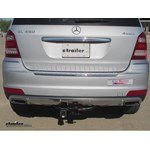
Video Transcript for Traile Wiring Harness Installation - 2010 Mercedes-Benz-GL-Class
Today on our 2010 Mercedes GL450, we'll be installing the Tow Ready ModuLite wiring harness with trailer pigtail, part number 119192. To begin our install, we'll first remove the driver and passenger side interior trim panels. Here on the passenger side, we'll simply turn the securing knob, unlocking it, pulling the panel out, and setting it aside. On driver side, we'll turn the knob, remove the door, then we'll need to remove the interior compartment. To do this we'll unlock both fasteners and then pull up and out on the box at the same time releasing it from any other points that secure it. Now on both sides, we can gain access to the manufacturers taillight wiring. Next, we'll need to test the wiring so that we can locate the circuits for our running lights, brake signal, and turn signals as this is considered a 3-wire taillight system where each circuit is independent from each other. To test out lights, we're going to go ahead and remove the connector from the back of the housing.
Now, we have access tot he taillight wiring connector, we'll use the test light to locate the correct circuit for each wire. Here on the driver side, we've located the olive wire with the black tracer will be the running light circuit, the red wire will be the brake circuit, and the black wire will be our left turn signal circuit. Here on the passenger, we'll use the manufacturers green wire with a black tracer. Now, we'll move back over to the driver side and start making our connections. It can be a little easier to make the connections if we remove some of the manufacturers tape and pull the wire loom apart. Now, we can go ahead and slide on the quick splice connector provided with the install kit and the follow it up with the wiring coming from our new Tow Ready harness.
Once the wire is in place, we'll crimp it down and close the clasp. We'll go ahead and repeat the process for our brake and turn signal circuit. Now, with our driver side connected, we can go ahead and take some black electrical tape and re-wrap the wiring harness. This will help to keep the wires together and wrap up our connection points to keep out any dust, dirt, debris, or moisture. Once we have the wires taped up, we'll go ahead and re-install the connector back into the taillight socket. At this point, we'll need to remove the rear threshold.
To remove the rear threshold, there are 2 fasteners that will need to be removed. These are T30 Torx bit screws. Once removed, we can then get underneath the threshold with a interior trim panel tool or a flat blade screwdriver and release the fasteners underneath the threshold. Once we have it popped free, we'll go ahead and turn it over and show you the fasteners. Now, we'll go ahead and set that aside.
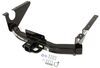
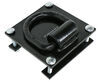
Take the green wire and run it from behind the interior trim panels on the driver side, underneath the threshold, and over to the passenger side. Here, we'll go ahead and make the same connection as we did earlier by removing the manufacturers tape, installing the quick splice connector, and then our Tow Ready harness wiring. We'll crimp it down and close the clasp. We'll re-tape the wires and then re-install the connector back into the socket. We'll leave our power wire over here this time as we'll cut off the excess later. Next, we'll take out white wire with the pre-attached ring terminal, which will be the ground wire for our module box, and attach it to the body of the vehicle using a self-tapping screw provided with our install kit. Now, we'll take out trailer wiring and feed it down underneath the vehicle. To do that we're going to go through one of the manufacturer's grommets here on the driver side. We'll go ahead and remove the grommet from the interior side panel, cut off one of the nipples of the grommet, and then feed the wire through the grommet. Once we feed the wire through, I'm going to go ahead and wrap up the wiring with some black electrical tape to help hold it together and protect it as it will be routed underneath the vehicle. We'll go ahead and feed it through the hole and then re-install the grommet. Next, we'll move underneath the vehicle and route the wire over to the center of the vehicle and down to the hitch. Now that we have our wire to the hitch, on this application, we'll be installing the Hopkins adapter 4-pole to 7-pole and 4-pole, part number 37185. To secure it to the vehicle, we'll be using the DrawTite mounting bracket for 7-way, part number 18138, and the DrawTite no-drill mounting bracket, part number 18136. To start, we'll take our 7-way connector and secure the 7-way mounting bracket to it using the hardware provided. Next, we'll go ahead and mount the 7-way bracket onto the no-drill mounting bracket. Now, before I install the bracket onto the vehicle, I'm going to go ahead and start wrapping up the wires with some black electrical tape. Once again, this will help to bundle up our wires and protect it from any of the outside elements. Note on this vehicle, we'll not be using the purple wire, which is for reverse taillights. The purple wire, we're going to go ahead and cut short. We'll go ahead and feed them through the hole in the bracket and install the bracket onto the vehicle. To secure the bracket to the vehicle, we'll use a worm-gear clamp provided with our no-drill mounting bracket. Now, with our 7-pole bracket secured to the hitch, we'll go ahead and start connecting our wires, stripping back both ends and adding the butt connectors in between. For this application, we'll be matching color for color. Once we've made all our connections, we can go ahead and wrap up the rest of our wires with some black electrical tape making sure to double up over the butt connectors to help prevent any dirt, dust, debris, or moisture from causing corrosion in these contacts. With that done, we'll need to secure the wiring up underneath the vehicle, keeping in mind when you route your wires, you want to stay away from any moving components, such as steering or suspension, or excessive heat such as exhaust. We'll run the wire up to the body lip. For this application, we'll be using a red line metal loom clamp, part number A0250, and a self-tapping screw. Once secured, we'll pull the excess wire back over underneath the driver side taillight assembly and then back up into the vehicle. Now, we'll move back to the driver side quarter panel. Here, we'll need to mount the converter box securing it to the manufacturer's wiring with a long black zip tie and then secure any of the wiring necessary to keep it bundles and out of the way. We'll cut off the excess of the zip tie to clean up our install look and then re-install the interior pocket and cargo panel. Next, we'll need to secure the wiring as it runs underneath the threshold over to the passenger side. To do this, I'm going to use a couple pieces of black electrical tape. This will be a temporary hold until the threshold is back in place. Then, we'll go ahead and re-install the rear threshold. Next, we'll move over the passenger side interior trim panel where we'll cut off the excess from our power wire. Next, we'll go ahead and prepare the fuse holder. To prepare the fuse holder, we'll cut it in half and strip back both ends. We'll add a ring terminal to one side and a yellow butt connector to the other. Next. We'll go ahead and strip back our power wire and then secure it to the yellow butt connector making our fuse holder inline with the power wire. Once we do that, we can once again go ahead and wrap up this connection point with some black electrical tape. Now, we'll go ahead and remove the nut from the positive battery post here in the fuse panel at the rear of the vehicle. Note that this application is not intended to come off completely, so we'll go ahead and back it off partially, and then, we'll use a pair of side cutters to cut a small slice into the ring terminal and fit it over the positive battery terminal stud. Then, we can re-secure the nut securing the ring terminal to the stud. With that done, we'll go ahead and install the fuse into the fuse holder and install the fuse holder cap. With that, that will complete the install. Next, we'll go ahead and show you how to test the new 4-pole connector. We'll simply take out test light and hook the ground clamp to the negative terminal. Then, using our test light, we'll test each point of our 4-flat connector, testing each one the other 3 terminals with the corresponding indicator starting next to the ground terminal will be the running light, then the left turn signal, left brake, and the right turning signal and brake. This will complete the install of our Tow Ready ModuLite wiring harness, part number 119192, on our 2010 Mercedes GL450. .
Customer Reviews
ModuLite Ultra Protector Wiring Harness w/ Integrated Circuit and Overload Protection - 119192
Average Customer Rating: 4.9 out of 5 stars (8 Customer Reviews)
This ModuLite Ultra Protector with integrated circuit and overload protection safeguards both itself and the tow vehicle against electrical shorts or mis-wiring situations.by: John04/16/2013
2013 Audi A-4
Regarding your adapter for trailer lights for my New 2013 Audi A-4. I
like the product. It works fine and the quality seems very good. Thanks.
However the directions leave a lot to be desired.
1- I wish it had a sheet saying how a car should be wired. For instance
you state that some VW-GTI's and some Mercedes have a "different" system .
that left me worrying that perhaps I had a different syst. because Audi has
always had amber taillights in the past, I was worried I might be hooking up
wrong. A list stating "2013 Audi A-4 - standard 2 wire syst."
2-I wish you would state clearly what a 2 wire syst. is and what a 3 wire
is. To a non professional installer it makes no sense. A non amber 2 wire
syst. has four wires including ground and a 3 wire has 5 wires inc ground.
It left me wondering if the new electronic cars somehow use two or three
wires.
3- The directions should have separate diagrams for 2 and 3 wire. the red
wire going to ground makes no sense as this seems like a hot lead to chassis
ground. Obviously it is not, but There was head scratching here. The label
on the wire itself cleared this up, but I was reading the directions and did
not notice the tag at first.
4- The wires should be labeled "in" and "out" It becomes obvious that the
short set is to connect into the rear corner of the car, but it would be
nice to confirm that.
5- The two green wires. These Must be marked better! One is about 12in.
longer than the other, and the short one is the same length as the out bound
wires. so I assumed that the short one was outbound and the long one goes to
the right corner for right directional. This was backwards. I now had to cut
both green wires and reverse them, which adds two more connectors in the
system than I would like.
I am an "advanced amateur" installer. I have probably installed about 30
taillight plugs on my various cars, both two and three wire. This is the
first in which I needed a wire from the battery. I would have certainly
appreciated a paragraph regarding why this is necessary. Not critical, but
helpful to understanding.
I appreciate that you make this product. The local Audi dealer has no
idea regarding this. The dealer said "go to a trailer place" I now have
working trailer lights on my New Audi. My business is selling and servicing
German Sailplanes. It is completely necessary to have trailer towing
capacity in my business for these lightweight 1400 lb trailers. A separate
instruction sheet with the above areas covered would go a long way to making
the installation of your very useful product much more simple.
by: Ron08/20/2013
2005 Dodge Ram Pickup
fast shipping and easy to install and fixed my 2005 dodge truck that didn't have left turn signal on trailer
Ron

8/21/2014
working great with this on the truck I dont have to worry about not having turn signals!
by: BROOKS08/11/2014
2003 Dodge Ram Pickup
Superior products with EXCELLENT directions enclosed within each packaged unit ordered! Will definitely use this site for any related needs!!
by: Paul B05/06/2019
Everything I've ordered has been on time and performed as it should. Will order again as needed.
by: Rhon11/19/2017
Product worked great. Installing it was easy.
Sadly the car was lost in Hurricane Harvey.
by: Matt02/18/2019
Works great!
by: George P03/30/2015
2010 Mercedes-Benz GL-Class
Exactly what I wanted and ordered. Shipped quickly
by: Gary 02/01/2021
8
8
See what our Experts say about this Tekonsha Custom Fit Vehicle Wiring
- Wiring Harness for 2015 BMW X3The ModuLite Ultra Protector Wiring Harness part # 119192 is missing a few parts when compared to the Upgraded Heavy Duty ModuLite Circuit Protected Vehicle Wiring Harness part # 119250KIT. The latter kit comes with a fuse holder, circuit tester, and 4-way trailer connector whereas the other does not. For your 2015 BMW X3 I highly recommend the ZCI Circuit Protected Vehicle Wiring Harness part # 119250KIT as you will need the circuit tester and this harness doesn't require splicing.
view full answer... - Where to Connect Power Wire for the Trailer Wiring Harness # 119192The power wire of the trailer wiring harness part # 119192 that you bought needs to connect directly to the positive battery terminal of the battery in your vehicle. It's purpose is to draw power directly from the vehicle battery for the trailer lights bypassing the vehicle's delicate wiring. If you were to power it from a fuse box like what you mentioned you'd not get the circuit protection and you'd void the warranty.
view full answer...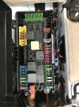
- Recommendation for Wiring a Camper to a 7-Way Wiring ConnectorWhat I would do in your situation is take a trailer side 7-way like the # H20046 and make an adapter out of it for your camper. So when the camper is in your truck you could just plug in the adapter to the 7-way located in the truck bed. Without knowing what the wiring of your camper is like I attached a picture of a chart that shows the wiring code of the # H20046 so you would know how to wire it to your camper. This will allow your trailer to still be able to use the 7-way at the rear.
view full answer...
- Trailer Lights Not Working on a 2008 Mercedes-Benz GL320 With ModuLite Ultra Protector 119192The ModuLite Ultra Protector Wiring Harness w/ Integrated Circuit and Overload Protection # 119192 has a re-settable short circuit and overload protection built in that protects itself and your 2008 Mercedes-Benz GL320 from electrical shorts and mis-wiring problems. This means that it will shut itself off and restart instead of allowing a fuse to blow. Since you have tested the functions on 7-Way of your GL320 and they seem to all be operating properly the problem is most likely on your...
view full answer...
Do you have a question about this Custom Fit Vehicle Wiring?
Info for this part was:

Expert Research:
Michael H

Expert Research:
Jameson C

Installed by:
Jeff D

Video Edited:
Joshua S

Test Fit:
Nicholas E

Updated by:
Laura H

Updated by:
Wilson B

Updated by:
Alexander C

Updated by:
Isabelle B

Updated by:
Manda E

Updated by:
Justice A

Video by:
Alan C
At etrailer.com we provide the best information available about the products we sell. We take the quality of our information seriously so that you can get the right part the first time. Let us know if anything is missing or if you have any questions.
Product Experts Available Now!
Call 1-800-940-8924
Dean
6/16/2014
did you install it or have a dealer install?