
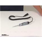
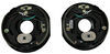
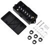
LCD Digital Circuit Tester
(22 reviews)
Price: $23.52
In Stock
LCD Digital Circuit Tester
Item # PTW2992
Retail:$35.73
Our Price: $23.52
You Save: 34%
In Stock
Thank you! Your comment has been submitted successfully. You should be able to view your question/comment here within a few days.
Error submitting comment. Please try again momentarily.


- All Info
- Reviews (22)
- Q & A (0)
- Videos (2)
- Photos
Performance Tool Electrical Tools - PTW2992
- Circuit Tester
- Testers
- Performance Tool
Features:
- Economy LCD Circuit Tester with LED back light
- Ideally used to detect power, voltage, ground, and circuit integrity
- Surge protected circuitry displays DC voltage from 3V to 48V (±0.3V accuracy)
- Conduct circuit tests with increased accuracy and ease
- LED indicates RED for power or GREEN for ground
W2992 Performance Tool LCD Digital Circuit Tester
W2992 LCD Digital Circuit Tester
California residents: click here


Video of LCD Digital Circuit Tester


Videos are provided as a guide only. Refer to manufacturer installation instructions and specs for complete information.


Video Transcript for Performance Tool LCD Digital Circuit Tester Review
Hi, they're hard workers! Today we're going to be taking a look at Performance Tool's LCD circuit tester. To give you an idea of how your circuit tester works, it has LEDs in here that'll light up when both power and ground is present. You'll have to clip your probe onto either power or ground. The, the clip end here, we've got that attached to the ground side of our battery. And then with the probe end, instead of the clip side, you'll touch this to your other circuit. And if there is the opposite there it'll light up.
So currently you've got ground on the clip side and our probe, or touching on the positive of our battery post and it lights up red. It also gives us a voltage reading on there, raking in about 12 and a half volts. Now we could swap this and hook it up the other direction. So we're hooking our clip onto positive, and then we're going to take our probe and touch it to ground, and it also lights up. But you will notice now that it's lit up green, letting you know that your probe side is touching on ground and you have power present on your clip side.
You'll also get a voltage reading there. And that's really nice that you get a voltage reading there, because if you have any drop across your circuit, you can help detect that as well. So you can kind of check out the integrity of your circuit while doing this. It's kind of a special thing here. Most of your test lights will just have a light on it.
It's really nice. And you've got that volt meter on there as well to get additional information. For example, currently now we're reading about 12 and a half volts, but if I was checking this further on down the circuit, and if we had some corrosion in that circuit, I may only read 12.1 volts further on down that circuit. And I know, Hey, the voltage has dropped from what it is here at the battery by a few tenths of a volt down there. Maybe I should look for a little bit of corrosion or a bad connection at that point.
And it may even drop even lower. You may only have like 10 or 11 volts and if you're checking it like that, then there's a good chance that you're finding, Hey, this is probably why I'm finding where my issue is. My item wasn't working. I was checking my circuits along the way, and I see a drop in voltage that's excessive, check your circuits there. So we're gonna go ahead and go through some examples of common uses of this and some, little bit more in depth tests that you can perform with a test light. Often people will use these to test the circuits at the back of their vehicle, and they usually do this when they plug up to your trailer and you find like, Hey, I don't have taillights or I'm missing a turn signal or something like that. Well, rather than immediately digging in and trying to fix some wires, let's figure out, Hey, where's the issue at is the issue on my vehicle side or is the issue with my trailer. That's where I like to start. So I've gone ahead and turned on the hazard lights in the vehicle, as well as the tail lights. And that should activate all of our signals. So we're going to take the clip here. We're gonna hook this on ground, which is the exposed stud there, so just flipping that on there, kind of putting the rubber boot off to the side here a little bit to help keep me from touching it. And now we're just gonna check our circuits. So here, we've got 12 volts here at the back. So we know that our taillight circuits working, and we've got a flashing signal there giving us our 12 volts so we know that that's working. And if we look at here, the color of the wire coming in, that's yellow, so that's gonna be our left turn signal. And then our right turn signal is the green wire. When we checked this one as well, we'd get our light lighting up and giving us our 12 volts. So we know that our vehicle side here is working properly. And this will also work when testing your six and seven way connectors as well. You just need to pay attention to what the circuits are. So for the four-pole ones, we we're able to turn on tail lights and hazards to get all these operational. With a seven way, you'll need a brake controller plugged in and somebody operating the output of it in order to be able to test that circuit, your auxiliary circuit should normally just have power on it all the time, but sometimes you have to start the vehicle to get the auxiliary circuit to come on. So just pay attention to those. So that way you know that you're getting the output back to your connector when you're checking, just verify that your vehicle has that particular output. In this instance, if we had an issue with our trailer though, we know that our vehicle's okay, so we can go ahead and button up this side. We don't need to diagnose anything over here. We would then turn to our trailer and try to figure out, okay, why, why is that signal not working So then we would do that from there. So here, we've got a scenario for you where we're going to show you a short to ground and how to diagnose it. Currently, I've got a scenario set up, so our board here, this is the load for our device. It's going off right now. And this just normally comes on when you put your vehicle in reverse. So let's say in our scenario, we put our vehicle in reverse, but instead of this, coming on, nothing happened because this was what a short to ground would be like, if there was a bare spot on your wire, it would spark a little bit. And what would eventually happen, it was over, it would overload the circuit and then it would pop your fuse. And if we take a look here, we can see that the fuse has blown. It's now open. So this was a temporary thing that we just put in there in place. But if you've got a short to ground in your trailer, it's likely always gonna be grounded out like that. So let's just go ahead and set that scenario up. So now we're in the current faulted state where we had started where the board was working, was the proper fixed state. We simulated a short to ground. So we're just gonna put this short to ground back so I'm stuffing that there. I'm just stuffing this in here just for simulation purposes. So now what's going to happen next is you go, oh, I got a blown fuse. Okay. Well, my fuse is blown. I'll just put another fuse in. And when you go to put another fuse in, you got to pull it back into reverse or operate, whatever accessory you're planning on operating, and it just pops the fuse again. Oh no. Well now, you know, you've got a real problem you gotta solve. Your test light can be a real wonder in these scenarios cause we can take that fuse out of there, Instead of wasting a bunch of fuses, what we can do is we can complete the circuit with our test light. And normally when you're doing this, you're probably gonna have to take a, a paper clip or something like that to clip into the other ends. And you can poke it down in there. So I'm gonna grab one of those real quick so we can mock that up. So now what we've done is we've taken our test light and we put it in place where the fuse used to be. The probe is in one prong, and then we used a paper clip and clipped it onto the clip side of the other side of the test light and put that in the other prong. And what you'll see there is that our test light has lit up. So what you'll want to check now is where, we know that this light's only gonna light up. if we've got a complete circuit that has a path all the way from power, all the way to ground, and then it'll light that light. So at this point you can put it in the particular state in which you're trying to activate, whatever it be, a light or whatever you're putting it in reverse to activate a light, go ahead and do that. We can see that's lit up. And now you would just start disconnecting circuits until you figured out an isolated where the short was. One of the things I like to do first, if it's easy to get to, is to take away the ground at the very end of the circuit, because our test light doesn't take very much current to amp, to light up. So if you think it's like a bulb or something, it can actually go through the bulb, so let's make sure that particularly at the ground at the very end of the circuit, So this is the load at the end. This is normally like a brake light bulb or something. You have your power that goes to the bulb or whatever your load is, and then the other side just goes right to ground. Well, if we remove this ground here at the end, what should happen is your test lights should turn out if there's no shorts, but if you look here, our test light's still lit up. That means that there's a path to ground still somewhere present. So you would work your way down the line to the next easiest connection point that you get to, and you would disconnect it there. If the test light turns off, then you know, okay, my short is between the point that I just disconnected there, and then a point further towards the back of the vehicle, back closer to the battery. If you just keep disconnecting circuits and the lights still light up, it is still lit up, then you know that you need to keep working your way towards the battery to find that issue. After I disconnect the one at the very back, what I usually do next is I'll disconnect the one here at the very front, and that way, I've eliminated between those two connectors and I can start finding that point. So we know our short to ground's here cause We did it here in this particular test scenario. But if we see if we disconnect this circuit there, we have no more test light turned on, cause it's no longer shorted to ground. So that can be a really useful test item to find short to ground without popping a bunch of fuses. Cause if you want to get power in the circuit to check for power, each time you'd have to put that fuse in there. And it probably end up blowing that fuse because of the current state it was in. But we can use our test light to get current through there and check it. Next we're going to show you guys how to perform a voltage drop test. And this is one of my favorite tests for finding difficult issues that can arise with circuits. Cause you could have a circuit that's completed, but still has high resistance or issues with it that can cause strange conditions to occur. So first thing we want to do is we're going to be using the volt meter portion of our test light now to do these tests. So whenever you're doing a voltage drop test, the first thing you want to do as a baseline test. We want to see what the voltage is at the battery. So we've got 12.4 volts right at our battery. We've got this lead on negative than on positive 12.4. We're going to use our test circuit once again. And I want to show you guys something neat. The circuit's complete, all that it needs ground to hook on, and then I'll turn on our board. This board does have a delay in it before it begins to activate the beeping. So we are going to get a little bit of time before it's going to go off on us there. But I wanted to show you guys that while we had 12 volts here at the battery, we check here at the ground connection where it's not disconnect, where it's not connected to ground. It's currently disconnected. Look at this guys. You got about 3.1 Volts there. So we still have some voltage that is present there. And in most cases, you're going to read very close to battery voltage here, unless the resistance gets too high. If we go ahead and clip this on ground, whenever you're checking like a light bulb or any kind of circuit, when you're checking your voltage drop, that can tell you the conditions of your circuit. So we're gonna complete the circuit by clipping this on. That'll complete our circuit here. So now if we check, this is on the ground side here, nothing. It doesn't even light up at all. Because all of our voltage should drop across our load. It should drop completely across here. If you still have voltage present on the other side, that typically indicates that you have a poor connection in here somewhere. I'm gonna go ahead and disconnect it to turn that off. But that usually indicates you've got a poor connection somewhere in here, because there was still some voltage present on the other side of your load. That means that there's corrosion or a bad connection. Maybe you got like two wires are barely touching here. That poor connection there, that high resistance, is actually consuming some of that voltage in order for it to get across that, to get to ground. And that can cause your lights to light up very dimly. If it's a computer module, sometimes it can cause it to wig out to where it does very unexpected things. So by doing your voltage drop test, that's one of my favorite ones to be able to narrow down those issues. And we're going to just run down this circuit here. So we're now at the battery, when we clip on here, we had about 12, four, and it's normal over the length of wire to see about a 10th of a volt drop. So we've got it right here at the battery, 12 three, we're gonna go right just the other side of our circuit protection. And we're right at about 12, 4, 12, 3. We haven't dropped any voltage yet. And then we heard up here to our tester but we can't quite get in there. 12 four still good there. And then we go right onto the other side here while it's activating and we get absolutely nothing. It's completely dropped across the circuit. You always want to see that. If you see something like, maybe you see like 10.4, more than likely, this thing's probably just dropping a little bit of voltage. You've actually really got a major issue on here on the ground side. The more voltage you have on the ground side of the circuit, past the load, the more issue, you know, you've got right here. The other thing we we're checking when we we're checking voltage drop there, we saw that it was nearly 12 four all the way up to our load. Let's say right here at the load, at the light bulb of whatever your load is, you're only measuring maybe like six volts. And of course your lights probably not gonna work, whatever here's probably not working properly. You know, between this point here and the battery up here, you had six volts that has dropped across that circuit. So you need to check the wiring between this point and that point to figure out why that voltage dropped. And again, it's typically going to be caused by a poor connection or heavy corrosion in that circuit. And that completes our look at Performance Tool's LCD circuit tester..
Customer Satisfaction Score:
99% were satisfied with this product
1% of customers were not satisfied
Customer Reviews
LCD Digital Circuit Tester - PTW2992
Average Customer Rating: 4.8 out of 5 stars (22 Customer Reviews)
by: Chad A04/11/2019
Used it twice it fried would not recommend. I bought the tester for general trailer repair for testing lighting circuits and all around diagnostics the one time that it did work it was nice to see the voltages but I just went back to my regular test light. Nothing like having a tool in your box that is garbage and not dependable. Buyer beware.
by: Bob M02/13/2018
This is an awesome product at a great price. Elsewhere online it was $100 so it was a large savings You can check ground just like a regular
trouble light but it light up green and you know how strong your ground is.Then you can check power supply then it lights red for power and lets you know the volts. I have tested my remote battery to find out it was weak it was below 3 new one tested 3.1 .I work in the auto field so it will be used to check batteries, charging systems, light sockets,window switches, ect. I love this tester I wont have to break out my ohm meter near as much.The tester appears to be very well built time will tell.For around $20 everyone should own one.
by: Weldon07/11/2018
These guys make that online big box store look like a minor league player. The shipping was fast, the product is great and works well. I will be ordering two more this week as everyone who borrowed mine loved the product. I already sold one to co-workers diagnosing electrical problems. The 48 volt capability makes this one tool capable of diagnosing weak batteries in parrallel and series wiring, measuring solar panel output, and diagnosing voltage draw a breeze.
by: Dave B04/15/2017
Excellent product. Just what is needed for all the new electronics systems. Computer safe, test circuits without fear of damaging equipment. The addition of the digital voltage readout is a big plus when testing and trouble shooting. Bought two, will order a third for the boat emergency tool kit. Invaluable tool for those pesky electrical gremlins.
by: Paul P06/12/2020
Great product at a great price. It sure came in handy. Thank You.
by: Michael 04/01/2021

Bauers H.

4/2/2022
Were a shop that specializes in hitch installs and this absolutely helps a ton in diagnosing wiring and testing for shorts in trailer wiring, the volt meter is unique to this brand and we have nearly 7 on hand because of that.
by: Nicholas02/13/2018
I received the item way earlier then expected and it works exactly as said and exactly as I need it to. Very high quality great for quick electronic diagnosis.
by: Montrey03/02/2018
Works great
by: Peter 08/26/2018
Great product work well
by: William 10/05/2019
great item, fast delivery, just what I ordered. Thank You
by: j d lule10/10/2017
good product at affordable price,
by: Keith M08/31/2017
Great product and excellent service
by: Gary 08/21/2023
by: Eugene 01/03/2022
by: Jerry 06/28/2023
by: Larry 05/03/2021
by: Daniel12/16/2022
by: Anthony 03/05/2023
by: Larry 04/07/2021
by: Jose 09/25/2020
by: Victor12/16/2022
by: John11/06/2020
22
22
See what our Experts say about this Performance Tool Electrical Tools
- Troubleshooting 3.6V Power on Brake Controller Circuit of 2011 GMC Yukon XLIt sounds like you are saying the brake circuit on the 2011 GMC Yukon XL (5 o'clock pin on vehicle 7-Way) has constant 3.6V no matter if the brake pedal or manual override on the brake controller is used or not. Start off by disconnecting the Yukon from the trailer and then testing the pin for the brake controller circuit with a circuit tester like # PTW2992 to see if there is constant power on the trailer side (could be backfeed from breakaway battery) or the vehicle side. If there is...
view full answer... - Troubleshooting No Power to Blue Output Wire for Brake Controller on 2012 Toyota TundraIt could be a fuse on your 2012 Toyota Tundra but I'm thinking that you either have a proportional controller like the P3 # 90195 or you aren't getting power from the cold side of your stop light switch when you press your brake pedal. Most proportional controllers like the one mentioned above have an internal inertia sensor so if your vehicle isn't moving it won't send much power (if any) back to the trailer brakes because it can sense that you are sitting still. This helps to keep your...
view full answer... - Troubleshooting Trailer Brake Lights and Trailer Lights That Work Individually But Not When Both OnSince the lights are working individually on the utility trailer it sounds like some sort of input issue on your vehicle. If you have an aftermarket powered converter on your vehicle you will want to use a Test Light # PTW2992 to test the wiring at the input and output of the converter to verify the correct circuits are getting power. You can also use this tester to follow the power through the trailer connection for any other shorts that you may be experiencing.
view full answer... - Adding Running Lights to Trailer with 5-flat ConnectorIt sounds like you have a 5-way flat on your trailer for the lighting functions; running lights, turning and brake and the fifth pin for the reverse lock out on a hydraulic brake coupler. The white wire on the light is the ground function and can be grounded to the trailer frame or spliced into the trailer connector ground wire. The brown wire needs to be wired to the running light circuit. Traditionally, the running light wire on a 5-way is brown but I am not sure which color wire is...
view full answer... - How to Tell if 12v Circuit on 7-Way is Active on 2019 Volkswagen AtlasYour 7 Pin connector should be active, especially if it was factory installed. You can test the connector with a circuit tester like our # PTW2992 when the vehicle is on. Then shut it off and test again to see if your connector is still drawing power with the engine off. If it is not active there is either a blown or missing fuse (check your owner's manual for location), or it possibly did not come active from the factory. In which case you can run a wire from the battery to the 7-way...
view full answer... - Troubleshooting a T-Connector Vehicle Wiring Harness for 2013 Ford ExplorerWe are going to begin a process of elimination to solve this problem, starting by checking the 7-way functions. Start by using a circuit tester such as # PTW2992, to test the individual outputs from vehicle's 7-way just to make sure they are all working as intended. If that proves to be an issue, we know the problem is on the Explorer's side, if not, we can narrow it down to the issue being on the trailer. You mentioned that you checked the ground on the Curt # C56278 harness, but be sure...
view full answer... - Testing Tail Light Wires to Install ZCI Trailer Wiring Harness on a 2018 Volkswagen Golf AlltrackWhile I do not know the wire colors/functions on your 2018 Volkswagen Golf Alltrack I can tell you how to figure it out. Use the included circuit tester that came with the ZCI harness # 119250KIT or if you need one you can get # PTW2992 to test the taillight wires while someone sits in the vehicle and goes through the various light functions. If there is one wire that has brake lights, taillights, and turn signals on it then you only use one connector per side on the ZCI harness. You...
view full answer... - Troubleshooting Lippert Electric Stabilizer Jacks Not Working With SwitchIf the motors on your Lippert High-Speed Power Stabilizer Jack # LC298707 do not work when you use the switch you will want to determine if you have a bad switch or if the jack is not getting power from the battery on your camper. First you will want to determine if power is getting to the switch. The red wire of the switch should have constant power from the battery. You can use a Circuit Tester # PTW2992 to test the voltage going into the switch. If you do not have power you will need...
view full answer... - Trailer Brake Controller Recommendation for a 2017 Tiffin Allegro Red MotorhomeWhile we do have brake controller options for your 2017 Tiffin Allegro Red Motorhome, on a 2016 Freightliner XCM chassis, we aren't aware of any plug and play connectors on the chassis itself. The only options we have require splicing but if you found a plug for a brake controller you can easily cut off the connector and splice a brake controller to that. For your application I recommend the Redarc Tow-Pro Elite # RED44FR because it installs out of the way (you only need access to the...
view full answer...
- Will Peterson Light Kit #M540 Replace the Lights on my Trailer?You would be able to add lights with the Peterson Light Kit for Trailers # M540 and since they have a new 4 way connection it should solve any issue you're having; that being said, I can run you through some quick steps to troubleshoot the lights on the trailer and avoid having to buy a new set of lights. It sounds like there may be an issue with the wiring harness on the vehicle or the trailer wiring that is keeping these lights from functioning, so I'll give you a couple of troubleshooting...
view full answer... - Troubleshooting Trailer Brake Output Connections to Electric Drum BrakesSince you have now adjusted the wiring to be correct and have set up your brake controller, the next thing to check is the output at your trailer connector. Use a circuit tester like # PTW2992 at that 5 o'clock brake output pin. It should show the connection on the controller as it draws power on that pin and then as you use the manual override it will increase in brightness as you apply more output power. If this is working, then you will want to connect your trailer and take it for...
view full answer... - Troubleshooting Trailer Wiring on 7-Way ConnectorFor your 7-way trailer connection, the basic wiring will include running/clearance lights, stop and turn left, stop and turn right, and ground. The other functions of a 7-way are reverse lights, electric brake output, and 12v power. The best way to connect the functions is using a circuit tester like # PTW2992 or # PTW2993 to test each function at the vehicle and then on the trailer when connected to the vehicle. I've attached a help article to assist with the connections. Keep in...
view full answer... - Hardwiring Installation of a Brake Controller on a 1998 Chevy BlazerOn your 1998 Chevy Blazer, you will have to hardwire the vehicle to install a Tekonsha Prodigy P2, # 90885. Hardwiring a vehicle may seem like a difficult task, but it really is not too hard. I can guide you through the process. You will need three items in order to install the brake controller. First, you will need the brake controller itself. Second, you will need a 7 and 4 Way Installation kit, # ETBC7. Last, you will need Draw-Tite Wiring, # 18252. First of all, you will need to install...
view full answer... - Replacement Mirror For 2011 Chevrolet Suburban With Electric Folding OptionThe K-Source Replacement Side Mirror - Electric/Heat w Signal, Lamp, Memory, Power Fold - Driver # KS62160G is not available without the glass; you would need to buy the entire assembly. This mirror has the electric folding option that you need and it is for the driver side; if you need the passenger side you can find it here # KS62159G. As a side note, I would make sure your current mirror is faulty and that it is not an electrical issue in the wiring circuit. If it is just an electrical...
view full answer... - Complete Setup For Towing A 3,500lb Trailer With A 2008 Honda OdysseyA few things will be necessary items if you plan to tow close to 3,500lbs with your 2008 Honda Odyssey. You will need a hitch receiver, trailer wiring kit, weight distribution hitch, and possibly a brake controller. It is always a good idea to also install a transmission cooler, power steering cooler, and suspension enhancement for safety and comfort. If you do not have a hitch receiver yet, I recommend the Draw-Tite Max-Frame Trailer Hitch Receiver # 75270. This has the highest weight...
view full answer... - How to Find the Wiring Configuration of Bargman 7-Way, RV-Style ConnectorThe Bargman 7-Way, RV-Style Connector # WG54006-043 uses the standard RV-style pin locations, but there is not an exact color-coded diagram because your wiring must match up by function, and not color. You would need to use a circuit tester like # PTW2992 to determine the correct functions and pair the trailer and vehicle wiring that way.
view full answer...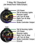
- Brakes are Only Applied to Trailer When Manual Override Switch is Being Used on a 2003 Ram 2500Before you get a new stop light switch, I would try testing the red wire that is connected to the back of your Prodigy P2 # 90885 with a Circuit Tester # PTW2992. You shouldn't get a signal until the brake pedal is pressed. If you do not get a signal, then you will want to test the OEM wiring for the stop light switch. If that is working just fine, then you will just need to replace the wire from your P2 to the OEM wiring on your 2003 Ram 2500. For a plug-in adapter use part # 3020-P,...
view full answer... - Troubleshooting Light Bar That Only Functions In The Accessory Ignition Position It sounds to me like the light bar was wired to the running lights which is why it works with your truck's ignition in the accessory position but cuts off when you start the engine. You can test this by checking the wire functions with a circuit tester like # PTW2992. Or simply turn your headlights on in your 2018 Ford F-350 Super Duty and check if the light bar is working. If this is not the case let me know and we can keep troubleshooting further.
view full answer...
- Connecting 12V Power Wire to Correct 7-Way Pin LocationIf you already have an adapter like the Hopkins Adapter 4-Pole to 7-Pole and 4-Pole # 37185 and you are needing to know what the Blue, Black,and Purple wires are used for, they are as follows: Blue - Brake Black - Hot Lead (12V Power Supply) Purple - Auxiliary (Usually Back Up) White - Ground Typically the 12V power supply is on the Black wire but you will want to verify that this is the correct for the 7-Way connector that you have. You can connect the Black wire to each of the 3 wires...
view full answer...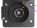
- Installing a Brake Controller on a 1994 Chevy Blazer From ScratchYes. We have numerous brake controls to choose from. Our most popular model is the P2, # 90885. But before you can start using it, there are a couple of things you will need, and some installations that need to be complete. First of all, you will need to install Curt Custom Fit Vehicle Wiring, # C55319. This is a simple T-One connector that plugs in line with your vehicles taillights. I have included the instructions and an installation video below. Next you will need to install a 7 and...
view full answer... - Is a 4-Way Harness Needed if My 2004 Honda Pilot Already has a Factory Installed 4-Way ConnectorOrdinarily, you would need three components to complete a brake controller and trailer wiring set up on a 2004 Honda Pilot. The brake controller, the 7 and 4 Way Installation Kit, # ETBC7, and wiring harness 43105 or 118336. If you already have a 4-Way connection at the rear of the vehicle, you should only need the brake controller and the ETBC7 kit. You have to make sure your 4-Way connection you have currently on the vehicle is functional (it is wired and ready to use). The ETBC7 kit...
view full answer... - Vehicle Wire Harness Replacement 7-Way OEM Connector For 2004 Chevrolet SilveradoThe factory wiring on your 2004 Chevrolet Silverado may vary and should be tested with a Test Light # PTW2992 before completely installing a Pigtail Wiring Harness # PK11998. With this harness you will be able to use a 7- and 4-Pole Trailer Connector Socket # HM40975 that uses an OEM connector. Silverado Wiring Light Green - Backup Lamps Dark Green - Right Turn and Stop Blue - Electric Brakes Yellow - Left Turn and Stop Red - Battery Brown - Running Lamps Black - Ground Pigtail Wiring...
view full answer... - Troubleshooting Trailer Lighting When Connected to 2019 Chevy Silverado 3500It sounds like you have a bad ground connection or some corrosion on your trailer side of the wiring. Since the vehicle you are using is a brand new 2019 Chevy Silverado 3500 I would be very surprised if the issue was on your vehicle side of things. You can easily confirm this by either connecting your trailer to another vehicle to see if the problem persists or use a circuit tester like part # PTW2992 to test the functions on the 7-Way of your Silverado (see attached). Looking at the...
view full answer...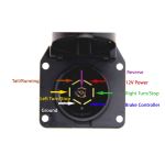
- Troubleshooting Reverse Light Function Not Working for New LED Lights on 1990 Jeep YJSince I don't know what LED lights you purchased for your 1990 Jeep YJ but I'm pretty sure the 4th wire is for your reverse lights and that you have your ground connected to your reverse light function. For example, the Jeep-Style LED Combination Trailer Tail Light # STL60RLBP for driver side and # STL60RB for passenger side, have 4 wires which connect to the following functions: White wire for ground Black wire for tail light and license plate light Red wire for stop/turn signal Yellow...
view full answer...
Do you have a question about this Electrical Tool?
Info for this part was:

Expert Research:
Jameson C

Expert Research:
Victoria B

Video by:
Dustin K

Installed by:
Cole B

Installed by:
David F

Video Edited:
Chris R

Written by:
Mary K

Updated by:
Wilson B

Updated by:
Erin H
At etrailer.com we provide the best information available about the products we sell. We take the quality of our information seriously so that you can get the right part the first time. Let us know if anything is missing or if you have any questions.
Product Experts Available Now!
Call 1-800-940-8924
Paul P.
6/14/2021
Just fine. Thank you.