

Installation Of Hopkins Agility Brake Controller # HM47294 On My 1992 Ford Bronco
Question:
I am installing this controller to a 1992 ford bronco 5.8 litre. The trailer I am towing is a 2 axle trailer with brakes on 1 axle. The installation kit is not available. Can you email me a wiring diagram ?
asked by: Russell S
Expert Reply:
When installing the Hopkins Agility Brake Controller, part # HM47294, on your 1992 Ford Bronco, you will not need the Ford adapter, part # HM47715, as it is not compatible with your 1992 Ford Bronco.
To install the Hopkins Brake Controller # HM47294 on your 1992 Ford Bronco, you will need to install a 4-Way Connector, the T-Connector Vehicle Wiring Harness, part # C55350, if you do not already have a 4-Way on your vehicle. You will need to use Brake Controller 7 & 4 Way Installation Kit, part # ETBC7, which will give you a 7-Way on the rear of your Bronco.
Begin, by installing part # C55350 which will plug in-line with your vehicles tail light harness, which is located underneath the vehicle, behind the rear bumper.
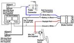
Then, you will need to install part # ETBC7. Begin by plugging in the 4-Way Connector of part # 118350 into part # ETBC7 and then connect the remaining wires. The White wire is the ground and should be connected to the frame of vehicle. The Black wire will be connected to the Black wire inside the duplex cable and ran to front of vehicle and connected to the positive battery terminal via included 40 amp circuit breaker. The Blue wire will be connected to the White wire inside the duplex cable, and ran to the front of the vehicle and later will be connected to the brake controller. The Purple wire can be connected to the reverse lights if the trailer has reverse lights or can be taped off and tied out of the way if not being used.
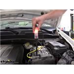
Now, you are ready to install the brake controller. The White wire on the brake controller will be connected to the negative battery terminal. The Black wire will be connected to the positive battery terminal via 20- or 30-amp circuit breaker, as specified in the brake controller instructions. The Blue wire will connect to the White wire in the duplex cable that you ran up earlier. The Red wire will be connected to the stoplight switch near the brake pedal, which only has signal when the brakes are applied. You will need to use a circuit tester, part # PTW2993 to find this wire.
I have linked instructions for the Hopkins Agility Brake Controller, part # HM47294, the T-Connector Vehicle Wiring Harness, part # C55350, and the Brake Controller 7- & 4-Way Installation Kit, part # ETBC7. I have also linked an FAQ on installing a brake controller from scratch, which shows a diagram of the wiring.


Products Referenced in This Question
Curt T-Connector Vehicle Wiring Harness with 4-Pole Flat Trailer Connector

- Custom Fit Vehicle Wiring
- Trailer Hitch Wiring
- No Converter
- Custom Fit
- 4 Flat
- CURT
more information >
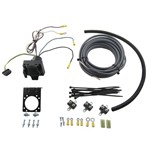
Universal Installation Kit for Trailer Brake Controller - 7-Way RV and 4-Way Flat - 10 Gauge Wires

- Accessories and Parts
- Trailer Brake Controller
- Installation Kits
- etrailer
more information >

Product Page this Question was Asked From
Hopkins Plug-in Simple Brake Wiring Adapter - Ford

- Accessories and Parts
- Trailer Brake Controller
- Wiring Adapter
- Plugs into Brake Controller
- Vehicle Specific
- Hopkins
more information >
Featured Help Information
Instructions
Miscellaneous Media

Continue Researching
- Article: Brake Controller 7- and 4-Way Installation Kit (ETBC7)
- Q&A: Adding a 7-Way Trailer Connector to a 2013 Ford F-150 that Came with Factory 4-Way Flat
- Q&A: Spindle Dimensions of a 3500 lb Axle
- Article: How to Adjust Your Trailer Brakes | The Ultimate Guide
- Article: Testing Trailer Brake Magnets for Proper Function
- Q&A: Heavy Duty Replacement Landing Gear Motor For Venture M-9000-PK
- Q&A: Replacement for Dexter 8-283 Hub/Drum
- Q&A: Replacement Trailer Hub/Drum for Part Number 2420801
- Q&A: How To Mount Two Friction Sway Control Bars On a Ball Mount
- Q&A: Replacement Trailer Lights with Numbers PM 143 and PM 421
- Article: Brake Controller Installation on a Full-Size Ford Truck or SUV
- Article: Brake Controller Installation: Starting from Scratch
- Article: Slipper Spring Trailer Suspension System Review
- Article: Flat Towing Package for 2011-2014 Ford F-150