bing tracking image

Brake Controller 7- and 4-Way Installation Kit (ETBC7)

The Brake Controller Installation Kit, or ETBC7, includes everything necessary for converting your 4-way connector to a 7-way connector in order to use a brake controller to activate the electric brakes on your trailer.
Select your vehicle to confirm the Trailer Brake Controller fit
brake controller fitguide

Why do I need an ETBC7?

If you do not have a 7-way plug on your vehicle, but want to use your electric trailer brakes, you will need to upgrade your wiring to support the brake controller. The ETBC7 includes everything you need to make this upgrade (once a working 4-way connection is installed).
Parts included:
  • 7-way trailer connector, which includes a 4-pole adapter plus 4 additional wires that connect to your vehicle to complete the installation
  • Mounting bracket and mounting hardware that secure the 7-way connector to the vehicle bumper or hitch; self-tapping screws mount the bracket to the vehicle and the trailer connector to the bracket
  • Black loom, which is a hard plastic tube that covers the 12-volt hot lead and brake wire connections, giving your installation a professional appearance and extra protection
  • Gray duplex cable that houses 2 wires that will become the 12-volt hot lead and electric brake wire, which run from the trailer connector to the front of the vehicle
  • Circuit breakers, which are used to protect electrical components against overload (3 are provided, 2 are used)
  • Butt connectors for securing connections between wires
  • Ring terminals, which attach to the ends of wires and hook around battery posts and circuit breakers
  • Quick splice wire connectors, which are used to quickly connect wires together
  • Zip-ties, which bind loose wires together and keep them in place, away from moving parts and exhaust system components
  • Circuit tester
ETBC7
Tools needed:
  • Drill
  • Ratchet socket set
  • Wire crimpers/strippers
  • Small utility knife
  • Phillips or flathead screwdriver

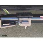
Brake Controller 7- & 4-Way Installation Steps

The ETBC7 installation kit works with your existing 4-way connector and brake controller. If you do not currently have a 4-way connector on your vehicle, you can use the Vehicle Wiring Fitguide to locate the custom-fit wiring harness, and the Brake Controller Fitguide to find the brake controller for your application. Since this kit supplements your brake controller, please review the instructions included with your brake controller before beginning the installation.
1. Find a suitable location to mount the 7-way connector plug.
  • A typical location is on the bottom of the bumper or on a bracket extending off your hitch
    • To mount on a hitch, use the included bracket plus a short or long no-drill mount bracket to achieve your desired bumper clearance.
    • Using the bolts, nuts and self-tapping screws, secure the mounting bracket into the bumper and the trailer connector into the bracket
install step 1
2. Plug the 4-pole adapter coming out of the 7-way connector into the vehicle's 4-pole trailer connector. Secure this connection with a zip-tie.
install step 2
3. Ground the 7-way connector by screwing the white wire with a ring terminal on it into the frame of the vehicle. If you will be using your reverse trailer lights, attach the yellow wire coming out of the 7-way connector to your reverse light wire, using one of the quick splice wire connectors included with the kit.
install step 3
4. Make a small cut in the rubber sheath of the duplex cable and slightly separate the two wires inside, being careful not to nick these wires.
install step 4
5. Use a butt connector to connect the black wire in the duplex cable to the 12-volt hot lead (black wire) on the 7-way connector. Then do the same for the white wire in the duplex cable and the brake wire (blue wire) on the 7-way connector. Use electrical tape to keep the wires together and then install the black loom over the wires.
install step 5
6. Route the duplex cable under the vehicle all the way up to the engine compartment under the hood, being careful to avoid hot areas or moving parts that might pinch the cable.
install step 6
7. Once the duplex cable is under the hood, you will need to separate the white brake wire from the black 12-volt hot lead. Cut away the gray sheathing as before, being careful not to nick the wires.
install step 7
8. The black 12-volt hot lead will stay under the hood, where it will be connected to the positive post of the battery by using a 40-amp circuit breaker. You will then route the white brake wire through the firewall (on the driver's side under the dash) into the vehicle, where you will connect it to the blue wire on the brake controller.
install step 8
9. Look for a grommet or knockout in the firewall to route the white brake wire into the cab. If none is available, you can drill a hole on a section of the firewall where there is no obstruction on either side. You will need to drill a hole to install a grommet large enough for the 3 wires that will pass through:
  • White brake wire from duplex
  • Power wire for brake controller
  • Ground wire from brake controller
install step 9
10. Using a butt connector, connect the blue wire coming out of the brake controller to the white brake wire from the duplex cable that was routed through the firewall.
install step 10
11. Mount the 20-amp (or 30-amp; see brake controller instructions) and the 40-amp circuit breakers in a safe location under the hood. In this photo, you will see it was mounted to the right of an existing ground wire on the firewall.
install step 11
12. The 12-volt hot lead from the trailer connector in the duplex wire (black) gets routed to the 40-amp breaker. Cut the extra wire and add a ring terminal. Attach to the AUX/silver post of the circuit breaker and route a wire from the copper post of the circuit breaker to the positive post on the battery.
install step 12
13. The black wire coming out of the brake controller is the brake controller power supply. It will be too short to reach the battery, so you will have to use excess wire from the duplex cable to complete this connection. Route this wire to the AUX/silver post on the 20-amp (or 30-amp) circuit breaker under the hood. Then route a wire from the AUX/copper post of the circuit breaker to the positive post on the battery.
install step 13
14. There are now two wires connected to the positive post: the 12-volt hot lead and the brake controller power supply. 15. The white wire coming out of the brake controller is the ground wire. Route this wire to the negative post on the battery. It will be too short to reach the battery, so you will have to use excess wire from the duplex cable to complete this connection.
install step 14/15
16. Inside the cab, only one connection remains. Find the wires connected to the brake stop light switch at the top of the brake pedal. Using a circuit tester, test the wires to locate the wire that carries a signal only when the brake pedal is engaged. Using a quick splice wire connector, connect that wire to the brake controller red wire.
install step 16
17. With the brake controller mounted and connected, zip-tie any loose, excess wires underneath the dash and under the vehicle. Clip any excess material from the zip-ties. Do not allow the wires to interfere with the brake and gas pedals and keep them away from areas that get very hot. Using a circuit tester, test all wires to ensure that they are getting power before you hitch up your trailer.
install step 17
wiring diagram
# ETBC7 Installation Diagram
For more information on brake controllers and wiring, see the following related articles: Updated by: Jacob JLast Updated: 3/14/2023


Departments

Towing

Sports and Recreation

Trailer Parts

Vehicle

What our customers are saying:

"very easy to shop"

Mike
Richmond, CA

Popular Vehicles