

How to Test Operation of TowReady Part # 118253 Honda Pilot Replacement OEM Tow Package Wiring
Question:
I just installed part # 118253 on my 2009 Honda Pilot. Now that the install is complete how do I check to make sure it works? I have a test probe but what prongs do I connect it to on the seven prong outlet?
asked by: Joe P
Expert Reply:
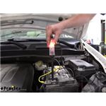
If it is not convenient to attach a properly functioning trailer to your vehicle to test the new wiring package, you can test each function (tail light, brake light, turn signal, etc) by using your test probe on each pin at the vehicle 7-way connector.
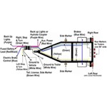
A helper will make this process easier as you will need someone to activate the lights and brakes while you apply the test probe to the corresponding connector pins. I have attached a link to a help article concerning trailer wiring. This provides detailed wiring information and diagrams including the output pin location for each function. Since your wiring harness uses a 7-way connector, you can refer to that specific section of the article. I have also attached a photo of the appropriate image that shows the connector pins in detail.
Select a pin and function for testing; for example, the pin at the 9-oclock position on the vehicle connector that activates the left turn signal and left brake light. Ground your test probe (like the tester # PTW2993). Engage the left turn signal. Apply the test probe to the connector pin at the 9-oclock position. This pin should carry an intermittent (blinking) signal. Now turn off the left turn signal and have your helper apply the brake pedal. This same pin should now carry a steady voltage for the brake light. Repeat these two tests for the right-side signal/brake pin at the 3-oclock position. Next repeat this process on the taillight pin (at the 11-oclock position) while your helper turns on the vehicle lights to test the tail and running lights. Continue this process on the reverse light pin (at center) with the engine off, key in the on position and the transmission shifted into reverse gear. Last test the brake controller output pin (5 o-clock position) while your helper depresses the brake pedal. Note that if you have a proportional-type brake controller you will not read any voltage to the output pin unless the controller manual switch is activated; a time-delay type controller will send voltage to the connector pin if the brakes are pressed or if you engage the manual switch. I have also included a link to a help article about brake controllers.
If all of these steps reveal an appropriate signal on each connector pin, you have confirmed correct functioning of your new wiring harness. In the event that one or more of these output pins does not carry the correct signal you should ensure that all wiring connections are correct and secure.


Products Referenced in This Question

Product Page this Question was Asked From
Tekonsha OEM Replacement Vehicle Wiring Harness with 7-Way Trailer Connector

- Custom Fit Vehicle Wiring
- Trailer Hitch Wiring
- Powered Converter
- Custom Fit
- 7 Round - Blade
- Tekonsha
more information >
Featured Help Information
Instructions
Miscellaneous Media


Continue Researching
- Article: Brake Controller 7- and 4-Way Installation Kit (ETBC7)
- Article: Wiring Trailer Lights with a 7-Way Plug (It's Easier Than You Think)
- Q&A: What is the Difference Between a 4-Way and 7-Way Trailer Connector
- Article: Trailer Wiring Diagrams
- Q&A: Recommended Hitch and Wiring Harness for a 2024 Kia Telluride
- Q&A: 7-Way Connector Wiring for a 2013 Honda Ridgeline
- Q&A: Installing 7-Way Trailer Connector on 2007 Honda Ridgeline
- Q&A: Brake Controller and Installation Harness Recommendation for a 2007 Honda Ridgeline
- Q&A: What is the Difference Between a Class II and a Class III Hitch?
- Article: Towing a Trailer? Let's Talk About Brake Controllers
- Q&A: Does Buyers Products Hitch Plate - Ford 3371809060A Include Mounting Hardware?
- Article: Wiring Trailer Lights with a 5-Way Plug (It's Easier Than You Think)
- Article: 2005-Current Volkswagen Touareg, Audi, or Porsche Cayenne
- Article: Brake Controller Installation: Starting from Scratch