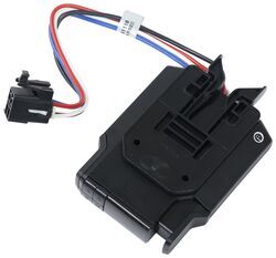
Finding Stoplight Circuit in 2004 Chrysler Town and Country for Installing Brake Controller
Question:
On a 2004 TandC, the brake switch has the following connector signals: 1 A103 18GY/RD FUSED B+ 2 L50 18WT/TN DIESEL PRIMARY BRAKE SWITCH SIGNAL 2 L50 18WT/TN GAS BRAKE LAMP SWITCH OUTPUT 3 V30 20VT/WT GAS S/C BRAKE SWITCH OUTPUT 4 V32 20VT/YL GAS SPEED CONTROL SUPPLY 5 Z429 20BK/OR GROUND 6 B29 20DG/WT SECONDARY BRAKE SWITCH SIGNAL The brakes work fine, but the outputs 2 and 3 of the switch go to the power distribution to light the bulbs, and have nearly 0 ohms, i.e., nearly grounded when the pedal is up, a condition warned against: IMPORTANT: Once a cold side wire is found, test to ensure that the wire is not grounded when the pedal is in the up position. If the wire is grounded, the brake control unit will be destroyed when manual control is used. To which wire do I attach the red controller wire?
asked by: Thomas W
Expert Reply:
When we installed the Curt Venturer part # C74VV in a similar 2010 Chrysler Town and Country we used the white wire with a green tracer for the stoplight circuit.
To test the wires for being a ground you would want to use a test like part # PTW2993 to probe the wire with one end of it and on the other attach it to a known 12 volt power source. If the light comes on then you know the circuit is grounded.
Check out the install video I attached that shows the Venturer installing on a 2004 Chrysler T and C.

Products Referenced in This Question
Product Page this Question was Asked From
Curt Venturer NEXT Trailer Brake Controller - 1-3 Axles - Time Delayed
- Trailer Brake Controller
- Time Delayed Controller
- Electric
- Electric over Hydraulic
- Automatic Leveling
- Under-Dash Box
- Dash Mount
- Up to 3 Axles
- LCD Display
- Up to 360 Degrees
- CURT
more information >
Featured Help Information
Instructions
Miscellaneous Media

Continue Researching
- Article: Brake Controller 7- and 4-Way Installation Kit (ETBC7)
- Q&A: 7-Way Trailer Wiring Harness for 2024 Hyundai Santa Cruz
- Q&A: How Does Curt TriFlex NEXT Brake Controller Mount
- Q&A: Mounting Panel For Redarc Tow-Pro Liberty on 2007 Toyota Tacoma
- Q&A: Parts Needed to Install the Prodigy P3 Brake Controller on a 2024 Honda Pilot
- Q&A: Recommended Suspension Enhancement For A 2019 Ram 1500 Bighorn 4WD
- Q&A: Which Connector Is Needed To Install Curt Spectrum Trailer Brake Controller On a 2018 VW Atlas?
- Article: Trailer Wiring Diagrams
- Q&A: Parts Needed to Install 7-Way/4-Way on 2024 Kia Telluride with LED Taillights
- Article: Towing a Trailer? Let's Talk About Brake Controllers
- Article: 2 Steps for Finding the Right Weight Distribution Hitch Size
- Article: Brake Controller Installation: Starting from Scratch
- Article: Using a Portable Generator on RV
- Article: 30-Amp and 50-Amp RV Service: What's the Difference?


