

Wiring a 2010 Honda Goldwing and Aspen Camper with a Prodigy RF Brake Controller
Question:
Okay guys, dont worry too much about the vehicles, the plugs/sockets etc, Ill concentrate solely on the electrical part, since this is where Im not familiar. The Gold wing AND the trailer have separate brake/indicator wiring, which prevents the Prodigy working right. I already have the bike wired with a 7-pin flat blade connector, but as you can imagine, it isnt entirely to the spec of the Prodigy pin 5 and 6 are indicator only, 2 is feed from brake lamp [non-LED]. It seems, that I need to amalgamate the brake/indicator on each side to enter into the Prodigy - any suggestions? Since the trailer is also separate brake/indicator, I will then need to switch back to separate upon exit from the Prodigy - any suggestions? Surely, there must be a simpler way to provide the Prodigy with the information it requires and perhaps modify the wiring of the 7-pin blade connectors. Since this doesnt have to move from vehicle to vehicle, it doesnt HAVE to be standard wiring, as it would be nice if everything went through the 7-pin blade connectors. Surely, most non-domestic vehicles are wired just like mine!! Im happy to follow directions and am fully able to carry out any complicated instructions or modifications, or if the bike/trailer needs to be modified, thats fine too apart from amalgamating brake/indicator. My main thought is that I dont want to spend many dollars with kits that I wont need.
asked by: James C
Helpful Expert Reply:

The Prodigy RF brake controller # TK94FR is expecting the brake and turn signals to be on the same circuit so you would want to combine those in order for the RF to work properly.
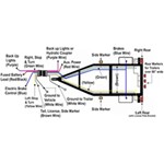
To do that you will need to use a converter on the bike side, # RM-732, to combine the circuits. On the input side, red is brake lights only, green is right turn only, yellow is left turn only, and white is ground. On the output side, green will be combined brake and right turn and yellow will be combined brake and left turn.
Wire the output wires to the bike side 7-Way.
Then, since the circuits are now combined, on the trailer side you will need to separate them back out AFTER the RF. To do that you will need converter # 118158. On this converter the input wires are green for combined brake and right turn and yellow for combined brake and left turn, and white is ground. On the output side you will have green for the right turn signal, yellow for the left turn signal, and red for brake lights.


Products Referenced in This Question
Vehicle to Vehicle Tail Light Converter

- Accessories and Parts
- Trailer Wiring
- Mounting Hardware
- Brackets
- 7 Round
- 7 Round
- Tow Ready
more information >
Roadmaster Brite-Lite Wiring Converter

- Flat Tow Wiring Harness
- Splices into Vehicle Wiring
- Tail Light Converter
- Universal
- Roadmaster
more information >
Product Page this Question was Asked From
Tekonsha Prodigy RF Wireless Brake Controller - Trailer Mount w Remote - 1 to 3 Axles - Proportional

- Trailer Brake Controller
- Proportional Controller
- Electric
- Automatic Leveling
- Remote Control
- Trailer Mount
- Digital Display
- Tekonsha
more information >
Featured Help Information
Instructions
Miscellaneous Media

Continue Researching
- Article: Brake Controller 7- and 4-Way Installation Kit (ETBC7)
- Article: Trailer Wiring Diagrams
- Article: Towing a Trailer? Let's Talk About Brake Controllers
- Article: Brake Controller Installation: Starting from Scratch
- Article: Wiring Trailer Lights with a 7-Way Plug (It's Easier Than You Think)
- Article: Curt Echo Full Review
- Q&A: Recommended Trailer Hitch For A 2024 Toyota Grand Highlander Hybrid With Dual Exhaust
- Article: Trailer Tire Sizing
- Q&A: What is the Difference Between a Class II and a Class III Hitch?
- Q&A: What is the Difference Between a 4-Way and 7-Way Trailer Connector
- Q&A: Availability of Trailer Hitch Receiver for 2022 Ford Escape PHEV
- Q&A: Brake Controller and Install for 2018 Chevy Colorado with Tow Package
- Q&A: What is the Best Grease for Trailer Bearings
- Q&A: Installing Trailer Brake Controller on 2019 Chevy Silverado 1500