bing tracking image

Brake Controller Installation for 2007 (New Body Style) - 2013 GMC Sierra and Chevy Silverado

When you install a brake controller on a 2007(new body style) through 2013 GMC Sierra or Chevy Silverado, you will have additional wires under the hood which make the installation slightly different from a typical installation. The following will take you through step-by-step through this installation process. Before installation begins, you will need 3 components:
  • Brake Controller
  • Brake controller adapter - Draw-Tite #20127 or Tekonsha #7894 Note: Adapters are only required for brake controllers with a quick disconnect feature. Brake controllers with wires attached do not need an adapter.
  • 7-way replacement adapter (unless already installed from the factory)

Installing the 7-Way Replacement Socket (PK11916)
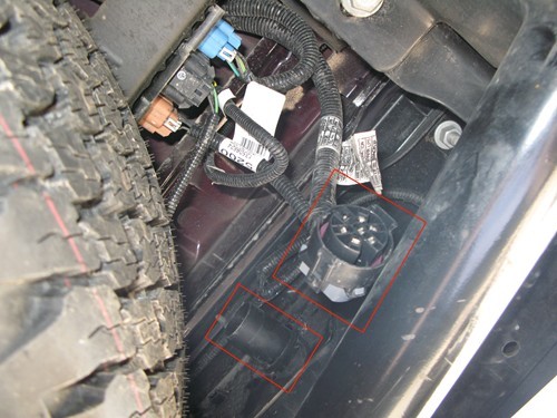
If your vehicle already has a 7-way trailer connector, skip ahead to "Connecting the Brake Controller Adapter (20127) to the Factory-Installed Tow Package."
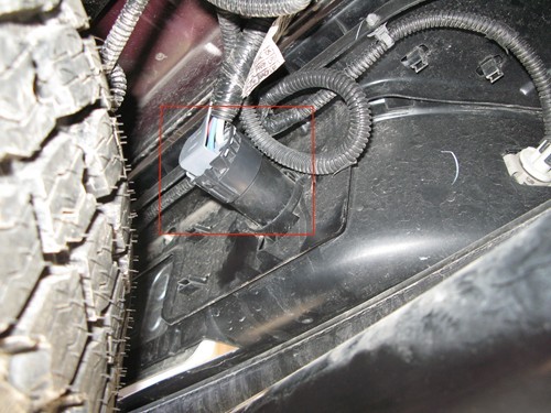
1. Begin at the rear of the vehicle, behind the bumper. Unplug the round 7-pole factory-installed plug that leads to the outside of the bumper. In the image below, the 7-pole factory-installed plug has been removed from inside the rear bumper.
Image: 7-Pole Factory Plug Removed from Inside Rear Bumper
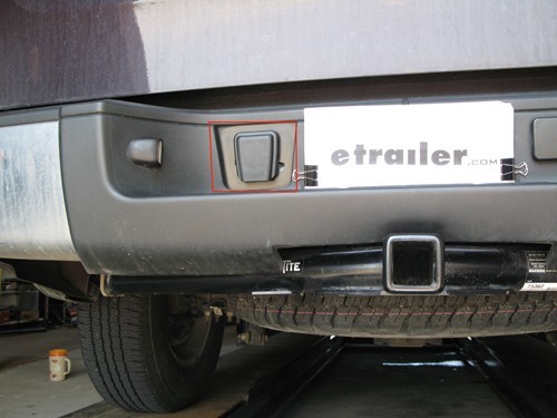
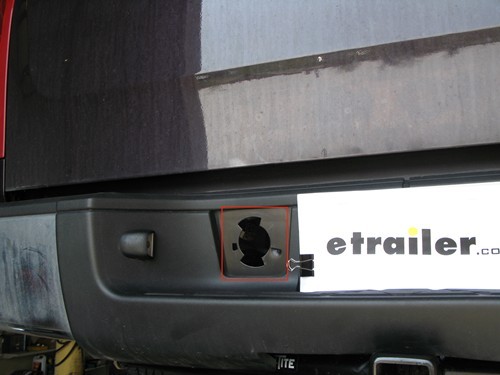
2. Move around to the outside of the bumper. Remove the square knockout panel, located to the left of the license plate. The images below show the square panel prior to and after removal.
Square knockout panel prior to removal
Square knockout panel removed
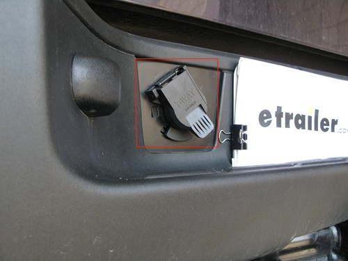
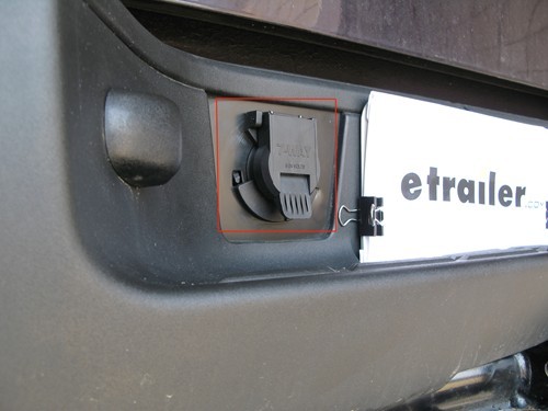
3. With the square knockout panel removed, slide the 7-way replacement socket (PK11916) into the knockout hole. Line up the notches on the replacement socket with the notches in the knockout hole. Then rotate the replacement socket clockwise, locking it in place.
Rotate the 7-way replacement socket clockwise
7-way replacement socket fully secured in knockout hole.
4. Return to the area behind the bumper. Insert the round 7-pole factory-installed plug (removed in step 1) into the 7-way replacement socket (installed in step 3).
Factory plug inserted into 7-way replacement socket
NOTE: It's always a good idea to use dielectric grease to help seal electrical connections. Water intrusion of the 7-way connector can cause shorts and corrosion in the wiring. In particular, shorting of the brake controller blue power wire may set off warning codes in the brake controller. Dielectric grease will keep moisture from compromising these connections.

Connecting the Brake Controller Adapter (20127) to the Factory-Installed Tow Package
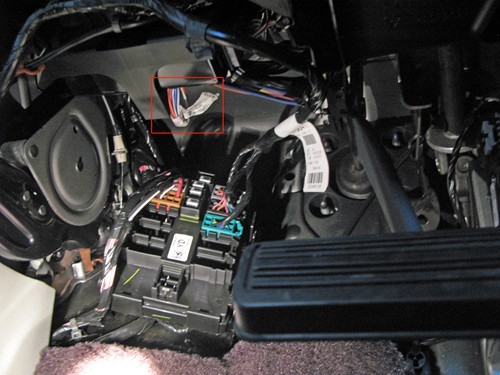
For brake controllers without the quick disconnect feature, no adapter is necessary. If your brake controller has wires already attached to the back, skip ahead to " Mounting the Brake Controller (Draw-Tite Activator III - 5520)".
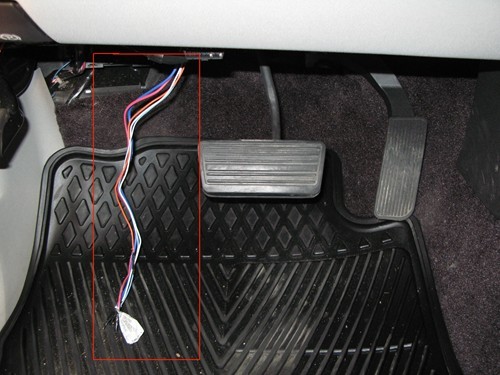
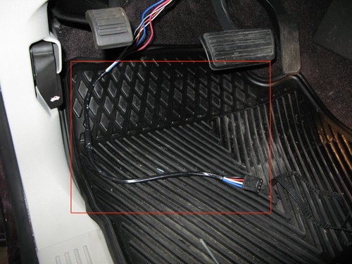
1. Below the steering column, there is a bundle of wires tied together with white tape, located left of the brake pedal. This bundle of wires is the tow package for the brake controller. Carefully cut the white tape binding the wires, and pull the wires down from underneath the steering column.
Tow package wires bound by white tape
Tow package wires pulled beneath steering column
2. Connect the four wires on the brake controller adapter (20127) to the tow package wires. Follow the table below to connect the tow package wires and adapter wires using butt connectors.
Tow Package WireBrake Controller Adapter
RedBlack
Dark BlueBlue
Light Blue or OrangeRed
WhiteWhite
3. Using electrical tape, bind the wires together.
Tow package wires bound with electrical tape

Mounting the Brake Controller (Draw-Tite Activator III - 5520)
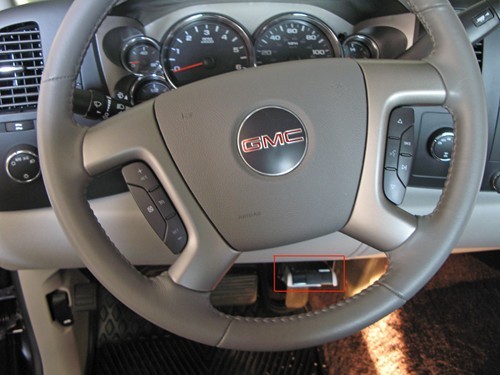
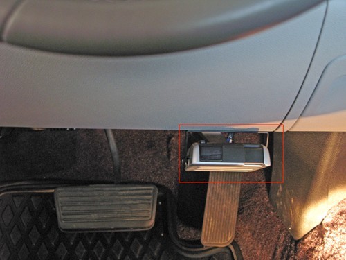
1. Choose an appropriate mounting location for the brake controller mounting bracket. A typical location is the lower right side of the dash, which allows easy access to the brake controller in the event of an emergency braking. 2. Using the screws provided, mount the mounting bracket into the dash. Make sure to avoid drilling through various components on the other side of the dash. 3. Using the screws provided, secure the brake controller into the mounting bracket.
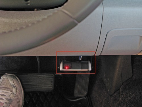
Brake controller secured into mounting bracket on lower right side of dash
Brake controller on lower right side of dash near brake and gas pedals
4. Plug the adapter (20127) into the back of the brake controller (5520).
Red light indicating brake controller is connected to adapter
5. With the brake controller mounted and connected, zip tie any loose, excess wires underneath the dash. Do not allow the wires to interfere with the brake and gas pedals, and keep them away from areas of excessive heat.

Finalizing Connections for the Brake Controller
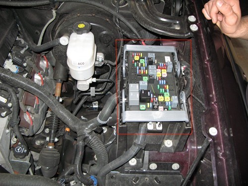
1. Under the hood, remove the cover for the power distribution box, located on the driver's side.
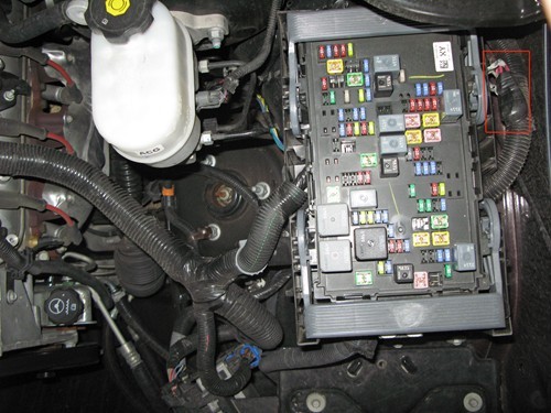
Power distribution box for brake controller
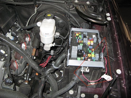
2. The ring terminal for brake controller power is located directly to the right of the power distribution box. It is taped to a wire harness between the driver-side front fender and the power distribution box. Cut the tape to release it from the harness. Then run the wire to the front of the power distribution box and hook the ring on the left post (M6 stud).
Power distribution box on the driver side (cover removed)
Brake controller power wire run to power distribution box
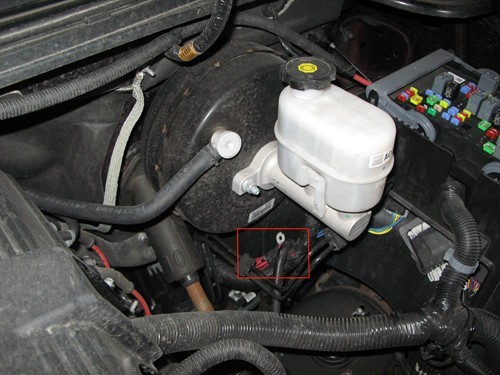
3. The ring terminal for the 12-volt power lead for the 7-way trailer connector is located to the left of the power distribution box. It is taped to a wire harness under the power brake booster. Cut the tape to release it from the harness. Then run the wire to the front of the power distribution box and hook the ring on the right post (M8 stud).
Ring terminal for 12-volt power lead
4. Tighten the ring terminals onto the posts using nuts (M6 and M8 nuts available separately).5. Activate the brake controller power post by inserting an automotive style 30-amp fuse into the correct slot in the power distribution box. 6. Activate the 12-volt power lead post by inserting an automotive style 40-amp fuse into the correct slot in the power distribution box. NOTE: Most vehicles are already equipped with the fuses listed in steps 5 and 6. However, if your vehicle does not have one or both fuses, you will need to insert your own fuses. 7. Place the cover back onto the power distribution box, and close the hood. NOTE: Most vehicles are already equipped with the fuses listed in steps 5 and 6. However, if your vehicle does not have one or both fuses, you will need to insert your own fuses.

Dave M.

7/16/2023

Awesome. Perfect to a "T". Done in 10 minutes. Ajax Ontario. 2008 Chevy Avalanche.

Etrailer Expert

Mike L.

8/2/2023

@DaveM Awesome! It's really cool when an install comes together that quickly!

Chris

5/1/2023

Where am I suppose to connect the red wire that’s under the break booster? It’s shows a pic of it but don’t see where it shows to connect it to. Do I connect it with the other red wire on 8m post?
Chris

5/1/2023

@Chris I have the Hopkins insight on a 2009 Silverado

Chris

5/1/2023

@Chris also confused about step 5 and 6 about the fuses. Can someone plz help with that?

Joe

4/28/2023

Do you guys know the part number for square knockout panel for 2007-2013 GMC Sierra and Chevy Silverado? Or do you guys sell the panel? Thanks.
Jd

7/23/2022

You guys are awesome I was going nuts with no power to the controller cause I was lead to believe that there was only 1 wire to connect to the box and I would never have found the one by the fender as it was pushed under the box. Thanks a whole lot guys

Joseph G.

5/22/2022

Your instructions are absolutely the best instructions that I have ever found when searching for "how to do" instructions. THANK YOU!

David B.

5/23/2022

*singing like Maui* You're welcome.


Departments

Towing

Sports and Recreation

Trailer Parts

Vehicle

What our customers are saying:

"You folks are fast. Thank you very much."

Peter
Ashland, VA

Popular Vehicles