

Installation Instructions Needed for Installing the Prodigy P2 and Wiring on a 1992 Chevy Astro Van
Question:
Hi, Looking to purchase a Prodigy P2 unit but I want to make sure I have all the necessary parts to install it to a 1992 Chevy Astrovan. Install instructions and parts list would be greatly appreciated! Thanks
asked by: C.Leonhardt
Expert Reply:
We have everything needed to install the Prodigy P2, item # 90885, on your 1992 Chevrolet Astro Van.
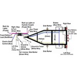
You will need to start out with a 4-Way trailer connector at the rear of your vehicle. If you do not already have one you can use the 4-Pole Hardwire Kit Including Circuit Tester, item # 18252, to install one. Use the included circuit tester to find the correct functions behind the vehicle tail lights. Connect the white wire to a good ground, the brown wire to the tail light circuit, the yellow wire to the left turn signal and stoplight circuit and the green wire to the right side turn signal and tail light circuit.
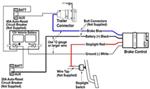
Next, you will need the Brake Controller 7 & 4 Way Installation Kit - 10 Gauge, item # ETBC7.
This kit includes the 7-way and 4-way connector and all of the remaining wiring and parts needed to complete the installation of the wiring for the P2 and the trailer connector at the rear of the vehicle. Connect the 4-way connector to the 4-Way connector on the back of the 7-way connector provided in the # ETBC7 kit. There will be 4 wires remaining. Attach the white wire to a good ground connection on the vehicle frame. The blue wire is connected to the white wire in the duplex cable provided in the kit and the black wire is connected to the black wire in the same cable. The remaining wire, purple or yellow, is for the vehicle reverse light circuit. If needed, it is spliced into the reverse light circuit behind one of the tail lights. If not needed it can be tied up out of the way with a zip tie.
Next, run the duplex cable forward to the engine compartment. Avoid areas that could pinch, cut or melt the wire. Under the hood, cut this wire off with enough length to run the black wire to the battery and the white wire into the cab of the vehicle to the mounting location for the brake controller. Use the included 40 amp circuit breaker and attach the black wire to it and then the positive battery terminal. Connect the white wire in the cab of the vehicle to the blue wire exiting the back of the brake controller.
Now, use the leftover duplex cable and connect the white wire to the white ground wire exiting the brake controller and the black wire to the black power wire exiting the brake controller. Run the cable through the firewall to the vehicle battery and connect the white wire to the negative post and connect the black wire to a 20 or 30 amp circuit breaker and then to the positive battery post.
The final wire connection needs to be made to the vehicles stop light circuit. Using a circuit tester find the wire that only has a signal when the brake pedal is pressed. This wire is located under the dash behind the brake pedal switch. Attach the red wire exiting the brake controller to this wire.
All that is left is to mount the brake controller in an accessible location and set it up for towing using the instructions from the brake controller you select. Links to wire installation instructions, instructions for the brake controller and items mentioned are provided below.


Products Referenced in This Question
4-Way Flat Trailer Connector w/ 72" Harness, Circuit Tester and Wire Taps

- Custom Fit Vehicle Wiring
- Trailer Hitch Wiring
- No Converter
- 6 Feet Long
- Universal Fit
- 4 Flat
- Tekonsha
more information >
Universal Installation Kit for Trailer Brake Controller - 7-Way RV and 4-Way Flat - 10 Gauge Wires

- Accessories and Parts
- Trailer Brake Controller
- Installation Kits
- etrailer
more information >
Product Page this Question was Asked From
Tekonsha Prodigy P2 Trailer Brake Controller - 1 to 4 Axles - Proportional

- Trailer Brake Controller
- Proportional Controller
- Electric
- Electric over Hydraulic
- Automatic Leveling
- Under-Dash Box
- Dash Mount
- Up to 4 Axles
- LED Display
- Up to 360 Degrees
- Tekonsha
more information >
Featured Help Information
Instructions
Miscellaneous Media


Continue Researching
- Article: Brake Controller 7- and 4-Way Installation Kit (ETBC7)
- Article: Trailer Wiring Diagrams
- Article: Brake Controller Installation: Starting from Scratch
- Q&A: Replacement Hub for 2013 Wildwood 26TBSS Hub Drum with AL-KO 8700
- Article: Towing a Trailer? Let's Talk About Brake Controllers
- Q&A: Wiring a Camper Shell Third Brake Light on a 2017 Chevrolet Silverado
- Q&A: How To Add a Fuel Tank To a Truck with 5th Wheel Hitch In Bed
- Q&A: Recommended 16' Mesh Tarp for Dump Trailer
- Q&A: How to Bleed Electric Over Hydraulic Trailer Brakes
- Q&A: What is the Estimated Installation Time for Firestone Ride-Rite Air Bags on a 2006 Ford F-250
- Q&A: Replacement LED Top Command Clearance Light With SAE-AP2-16 On Lens For 2018 Sunseeker Motorhome
- Article: Best Camper Jacks
- Article: How to Choose the Right Trailer Hitch Class
- Article: Wiring Trailer Lights with a 4-Way Plug (It's Easier Than You Think)