How to Test Brake Controller Wiring of Vehicle for Wiring to Controller
Question:
I wanted to find out the wiring diagram on the factory port brake controller in my truck. I have brought a Hopkins brake control connector #47755 and found that the wires on the factory does not match to the b.c. connector. I know what the b.c. connector 4 wires, black, blue, red and white is for, but the factory wires on it in order is: small white/tan tracer, large red/orange, large blue, small black/orange. I consulted the book Haynes manual and found that neither wires match to the inch typical wires listed in the book. Do you know where those wires go to and is it messed up in order?
asked by: Ian V
Expert Reply:
You are going to have to test the wires to determine their function and how they would wire to the brake controller. If the colors don't match what the OEM book you have says they should be then the only way is to test to be sure.
One of the wires should have power all the time. That would be the power source for the controller and would run to the black wire. One of the wires should have voltage only when the brakes are applied. That goes to the red wire of the controller. That leaves two wires. The brake output and the ground.
You will need to test for the ground wire. Ground the tester to the constant 12-volt power wire, then probe the remaining two wires. The wire that lights the tester will be the ground, the other will be the brake output circuit.

Product Page this Question was Asked From
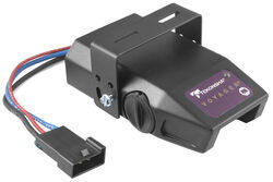
Tekonsha Voyager Trailer Brake Controller - 1 to 4 Axles - Proportional
- Trailer Brake Controller
- Proportional Controller
- Electric
- Manual Leveling
- Under-Dash Box
- Dash Mount
- Up to 4 Axles
- Indicator Lights
- Up to 90 Degrees
- Tekonsha
more information >
Featured Help Information
Instructions

Continue Researching
- Article: Trailer Wiring Diagrams
- Article: How to Choose the Right Trailer Hitch Class
- Q&A: Replacement Trailer Grease Seals for Allis 5013 29772
- Article: Brake Controller 7- and 4-Way Installation Kit (ETBC7)
- Q&A: Comparing the Curt Q20 and the Curt A20 5th Wheel Hitches.
- Q&A: Which Nev-R-Adjust Brake Assemblies for Load Trail 14K Dump Trailer
- Q&A: How To Add a Fuel Tank To a Truck with 5th Wheel Hitch In Bed
- Q&A: Wiring a Camper Shell Third Brake Light on a 2017 Chevrolet Silverado
- Article: Guide to Choosing the Best Truck for 5th-Wheel Towing
- Q&A: Kit to Convert 2021 Vanleigh Pinecrest 335RLP to Electric Over Hydraulic Disc Brakes
- Q&A: 10k Dexter Replacement Hub for a 8-415
- Article: Best Camper Jacks
- Article: Brake Controller Installation: Starting from Scratch
- Article: Wiring Trailer Lights with a 4-Way Plug (It's Easier Than You Think)


