

Installing a Tekonsha Voyager Brake Controller From Scratch in a 1993 Ford F-150
Question:
red wire goes to cold side of brakes,i have 1993 f 150 2 wheel drive. where is cold side of brakes located?
asked by: al b
Expert Reply:
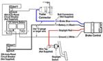
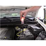
The red wire on the Tekonsha Voyager Brake Activator - Proportional, # 39510, connects to a wire on the brake light switch above the brake pedal. From the wires connected to the brake switch at the top of the brake pedal, find the wire carrying a signal only when the brake pedal is engaged. You will need a circuit tester like # PTW2993. Connect that wire to the brake controller red wire. The brake controller needs to be hardwired to install in your 1993 Ford F-150. For this installation, you will need Tow Ready Custom Fit Vehicle Wiring, # 118316, and a 7- and 4-Way Installation Kit, # ETBC7.
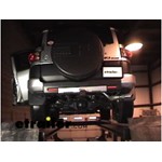
You will start by installing the Custom Wiring, # 118316. I have included a link to the installation details and a video installation below. Installation is simple. The T-one harness plugs in line with your vehicles taillight wiring.
After the Custom Wiring is installed, you will need to install the ETBC7 kit. This kit allows for a 7 or 4 pole connection at the rear of the vehicle. It plugs into the 4 way you just installed and connects to the brake controller and vehicle battery.
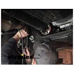
After installing the 118316, ground the 7-Way white wire of the ETBC7 kit onto the vehicle frame. Connect the black wire in the grey duplex cable (included with the ETBC7 kit) to the black wire on the 7-Way. Then connect the white wire from the duplex to the blue wire on the 7-Way. Next, you will route the duplex cable under the vehicle to the engine compartment. Be careful not to run the wire where it can be pinched or burned.
Next, mount the brake controller where you will have easy access to it using the bracket and screws provided.
Last is to make the connections from the brake controller to the vehicle. On the duplex cable, now under the hood, separate the white brake wire from the 12-volt black wire. The white wire gets routed through the firewall, under the dash, into the vehicle. This wire connects to the blue wire from the brake controller. The black wire gets connected to the positive battery terminal via a 40 amp circuit breaker. Mount the circuit breakers under the hood or dash, then route the black hot lead to the 40 amp breaker via ring terminals, and then to the positive battery terminal.
The black wire on the brake controller connects to a 20 or 30 amp circuit breaker (see the brake controller instructions for which circuit breaker to use) and then to the positive battery terminal. Route the brake controller white wire to the negative battery terminal. From the wires connected to the brake switch at the top of the brake pedal, find the wire carrying a signal only when the brake pedal is engaged. You will need a circuit tester like the Quickee # 3808. Connect that wire to the brake controller red wire. I have also included 2 videos that show the installation of an ETBC7 kit.
I have included an FAQ on wiring a brake controller from scratch that contains a little more detail.


Products Referenced in This Question
T-One Vehicle Wiring Harness with 4-Pole Flat Trailer Connector

- Custom Fit Vehicle Wiring
- Trailer Hitch Wiring
- No Converter
- Custom Fit
- 4 Flat
- Tekonsha
more information >
Universal Installation Kit for Trailer Brake Controller - 7-Way RV and 4-Way Flat - 10 Gauge Wires

- Accessories and Parts
- Trailer Brake Controller
- Installation Kits
- etrailer
more information >

Product Page this Question was Asked From
Tekonsha Voyager Trailer Brake Controller - 1 to 4 Axles - Proportional

- Trailer Brake Controller
- Proportional Controller
- Electric
- Manual Leveling
- Under-Dash Box
- Dash Mount
- Up to 4 Axles
- Indicator Lights
- Up to 90 Degrees
- Tekonsha
more information >
Featured Help Information
Instructions
Miscellaneous Media


Continue Researching
- Article: Trailer Wiring Diagrams
- Article: How to Choose the Right Trailer Hitch Class
- Article: Brake Controller 7- and 4-Way Installation Kit (ETBC7)
- Q&A: Comparing the Curt Q20 and the Curt A20 5th Wheel Hitches.
- Q&A: How To Add a Fuel Tank To a Truck with 5th Wheel Hitch In Bed
- Q&A: Wiring a Camper Shell Third Brake Light on a 2017 Chevrolet Silverado
- Q&A: Replacement LED Top Command Clearance Light With SAE-AP2-16 On Lens For 2018 Sunseeker Motorhome
- Article: Guide to Choosing the Best Truck for 5th-Wheel Towing
- Q&A: Kit to Convert 2021 Vanleigh Pinecrest 335RLP to Electric Over Hydraulic Disc Brakes
- Q&A: 10k Dexter Replacement Hub for a 8-415
- Article: Best Camper Jacks
- Q&A: Replacement Hub Needed for Lippert 122093 Hub on 5,200 lbs Axle
- Article: Brake Controller Installation: Starting from Scratch
- Article: Wiring Trailer Lights with a 4-Way Plug (It's Easier Than You Think)